Multi-beam and multi-band antenna system for communication satellites

a communication satellite and antenna system technology, applied in the field of radio frequency satellite communication systems, can solve the problems of low antenna efficiency, inconvenient band but not high frequency, and poor antenna efficiency

Active Publication Date: 2005-03-10
THE BOEING CO
View PDF13 Cites 48 Cited by
  • Summary
  • Abstract
  • Description
  • Claims
  • Application Information

AI Technical Summary

Benefits of technology

In yet another aspect of the present invention, a satellite communication system includes a radio frequency communication system and an antenna system connected to the radio frequency communication system. The antenna system includes a reflector having a non-frequency selective reflector surface. The reflector is sized to produce a required beam size at a K-band frequency. The reflector is oversized at an EHF-band frequency. The reflector surface is a synthesized surface of modified-paraboloid shape. The synthesized reflector surface is moderately shaped and disproportionately broadens EHF-band and Ka-band beams compared to K-band beams. The synthesized reflector surface forms a 0.5-degree beam at K-band, Ka-band, and EHF band. A multi-beam, multi-band feed array is located close to the focal plane of the reflector. The feed array includes a number of high-efficiency multi-mode circular horns. The feed array is focused at a K-band fre

Problems solved by technology

A single antenna system, however, that supports multiple frequency bands and multiple beams in each band simultaneously has not been observed in the prior art.
The lack of such systems may be due, for example, to the fact that a single aperture sized for a low frequency band typically produces a much narrower beam at the high frequency band, especially when the bands are widely separated (e.g. more than one octave band of separation).
Disadvantag

Method used


Image

  • Multi-beam and multi-band antenna system for communication satellites
  • Multi-beam and multi-band antenna system for communication satellites
  • Multi-beam and multi-band antenna system for communication satellites

Examples


Embodiment Construction

The following detailed description is of the best currently contemplated modes of carrying out the invention. The description is not to be taken in a limiting sense, but is made merely for the purpose of illustrating the general principles of the invention, since the scope of the invention is best defined by the appended claims.

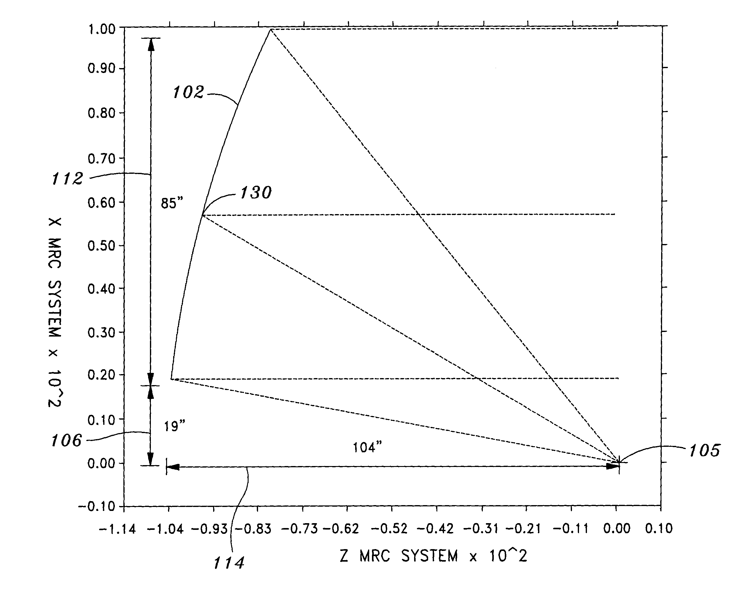
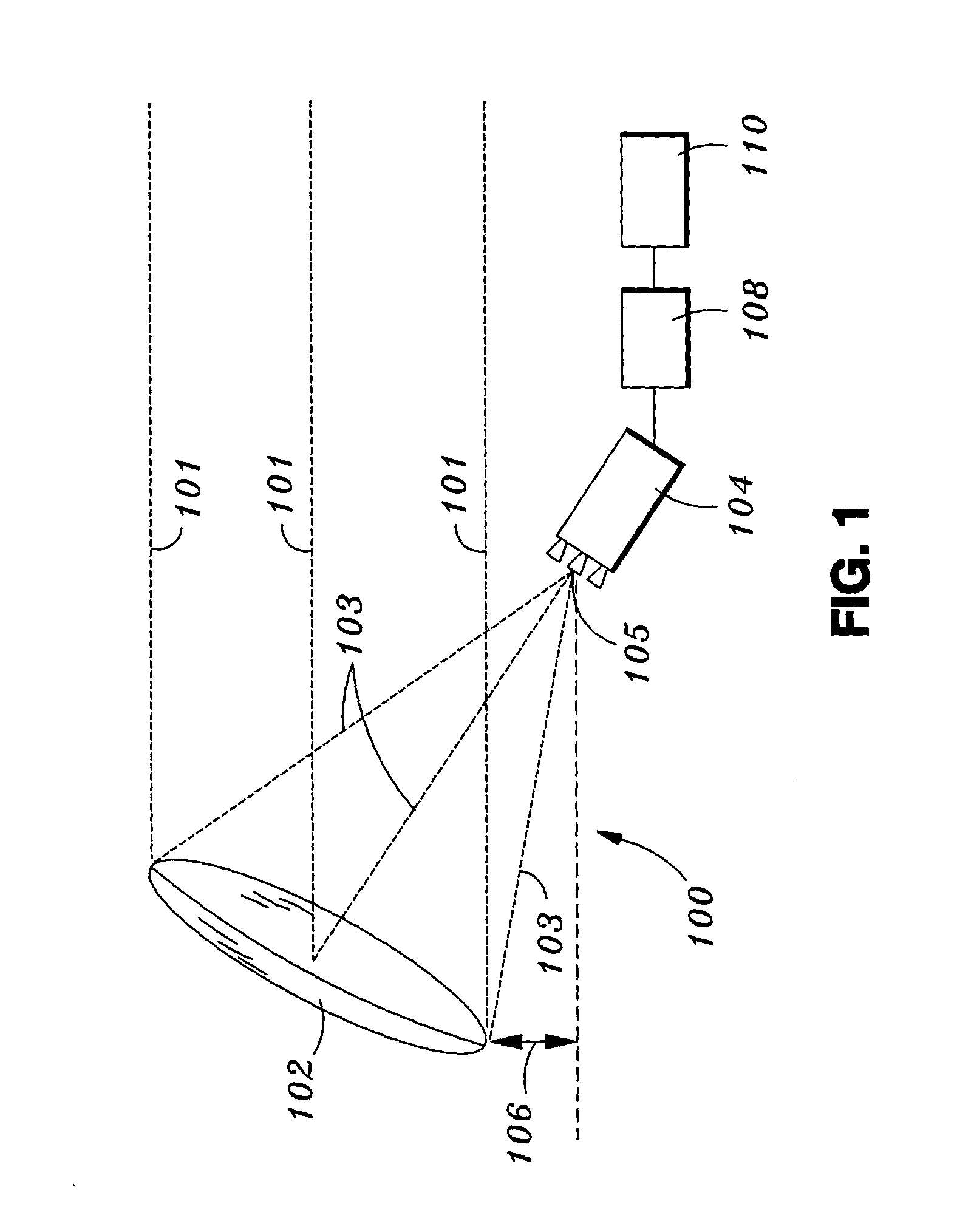
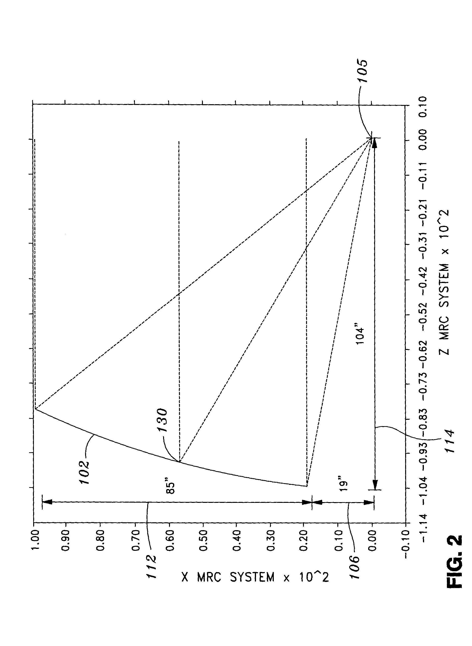
Broadly, an embodiment of the present invention provides propagation, i.e., transmission and reception, of radio frequency signals on multiple, widely separated frequency bands and in multiple overlapping spot beams at each of the frequency bands, that supports dual-circular polarizations for each beam and for each frequency band. One embodiment provides an antenna system, with enhanced capabilities, that is applicable to next generation satellite payloads, aircraft antennas, and ground terminals.

A single “multi-band” and “multi-beam” antenna, according to an embodiment of the present invention, may support multiple frequency bands and may also generate ...


PUM


Abstract

An antenna system includes a reflector having a modified-paraboloid shape; and a multi-beam, multi-band feed array located at a focal point of the reflector so that the antenna system forms a multiple congruent beams that are contiguous. The system has a single reflector with non-frequency selective surface. The reflector is sized to produce a required beam size at K-band frequencies and is oversized at EHF-band frequencies. The synthesized reflector surface is moderately shaped and disproportionately broadens EHF-band and Ka-band beams compared to K-band beams. The synthesized reflector surface forms multiple beams each having a 0.5-degree diameter at K-band, Ka-band, and EHF band. The multi-beam, multi-band feed array includes a number of high-efficiency, multi-mode circular horns that operate in focused mode at K-band and defocused mode at Ka-band and EHF-band by employing “frequency-dependent” design for the horns.

Description

BACKGROUND OF THE INVENTION The present invention generally relates to radio frequency satellite communication systems and, more particularly, to a multi-beam and multi-band antenna system for communication satellites and for ground / aircraft terminals that communicate with multiple satellites. Commercial as well as military communications have been evolving from single band systems to multi-band systems in order to achieve improved coverage, bandwidth, data throughput, and connectivity. The Defense Satellite Communications System (DSCS) systems use X-band (8 giga-Hertz (GHz)) while the Wideband Gapfiller Satellite (WGS) system being currently developed for U.S. Air Force uses X-band, K-band (20 GHz), and Ka-band (30 GHz) services. Future communication systems will be driven towards improved connectivity, anti-jamming performance, small terminal user support and increased data throughput. The Transformational Communications Architectures (TCA) studies are presently being conducted ...

Claims


Application Information

Patent Timeline
IPC IPC(8): H01Q5/00H01Q5/45H01Q19/12H01Q19/17H01Q25/00
CPCH01Q19/17H01Q5/45H01Q25/007
Inventor RAO, SUDHAKAR K.BRESSLER, DAVID
Owner THE BOEING CO
Why Eureka
Try Eureka