Adjustment method of dot printing position and printing system

a technology of printing system and adjustment method, which is applied in the direction of printing mechanism, spacing mechanism, printing, etc., can solve the problems of image degradation such as line misalignment, vertical ruled lines with low straightness, and line misalignment tend to be recognized

Active Publication Date: 2005-03-10
CANON KK
View PDF16 Cites 52 Cited by
  • Summary
  • Abstract
  • Description
  • Claims
  • Application Information

AI Technical Summary

Benefits of technology

[0021] The present invention has been accomplished to overcome the above problems and it is an object of this invention to provide a dot position adjusting method that can...

Problems solved by technology

In a printing apparatus that performs a bidirectional printing for an increased speed, if positions on a print medium of dots formed by a forward scan and of dots formed by a backward scan deviate from each other, an image degradation such as line misalignment occurs.
That is, when vertical lines perpendicular to the scan direction of the print head are formed by forward scans and backward scans alternately, the positions of dots formed by the forward and backward scans may fail to align, resulting in vertical ruled lines with low straightness.
Ruled lines are often printed in black and thus the line misalignment tends to be recognized as a problem encountered in black images.
The similar problem, however, also occurs with color images.
However, if a culling pattern used in the forward scan and a culling pattern used in the backward scan deviate from each other, a resulting image will become ununiform.
This ununiform image appears in a cycle that depends on the applied mask pattern, so when the entire image is looked at, an unpleasant pattern or texture shows over the entire image.
But if the dot deviation between the magenta and cyan print heads occurs only during a particular scan, only the areas printed by that scan show up their color difference in the form of bands, resulting in an uneven blue color image.
This method, however, not only is cumbersome for the user but also is not immune f...

Method used


Image

  • Adjustment method of dot printing position and printing system
  • Adjustment method of dot printing position and printing system
  • Adjustment method of dot printing position and printing system

Examples


Embodiment Construction

[0036] Embodiments of this invention will be described in detail by referring to the accompanying drawings.

[0037] (Construction of Printing Apparatus)

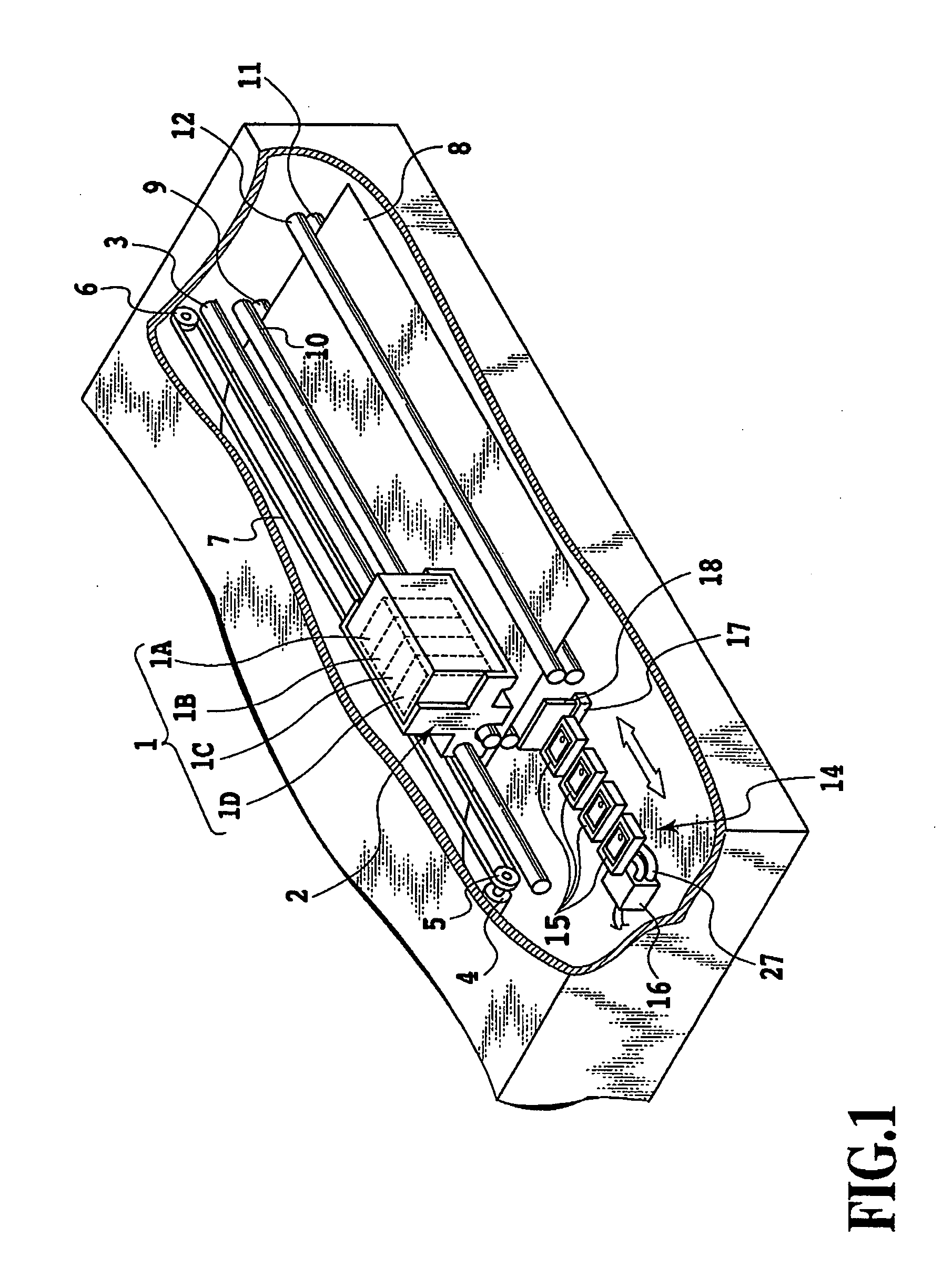
[0038]FIG. 1 is a perspective view schematically showing the construction of essential components in an ink jet printing apparatus that can apply this invention. In FIG. 1, reference numerals 1A, 1B, 1C and 1D represent head cartridges which are mounted on a carriage 2 so that they are individually replaceable. Each of the head cartridges 1A-1D is provided with a connector for receiving a head drive signal. In the following description the entire head cartridges 1A-1D or any one of them will be referred to as head cartridges (print head or print means) 1.

[0039] The individual head cartridges 1 eject inks of different colors. Ink tanks provided to the head cartridges 1 accommodate cyan (C), magenta (M), yellow (Y) and black (Bk) inks, for example. The head cartridges 1 are positioned and mounted on the carriage 2 so that they are ind...


PUM


Abstract

A print position adjusting method capable of executing dot adjust value calculation processing in ways that can meet diversified user needs of recent years, and a printing system that can realize the print position adjusting method are provided. Multiple kinds of dot adjust value calculation processing capable of acquiring an adjust value for aligning print positions are prepared, so that the user can select a desired one. With this arrangement, the user can execute the desired dot adjust value calculation processing as necessary.

Description

BACKGROUND OF THE INVENTION [0001] 1. Field of the Invention [0002] The present invention relates to a dot print position adjusting method in a dot matrix printing and to a printing system using this method. More specifically, the invention relates to a print position adjustment to align positions of dots formed by a forward scan and a backward scan in a bidirectional printing and to a print position adjustment to align positions of dots formed by a plurality of print heads. [0003] 2. Description of the Related Art [0004] Relatively inexpensive personal computers, word processors and other office equipment have proliferated in recent years. Under these circumstances, printing apparatus to print information from these devices and technologies to increase a printing speed and enhance an image quality of the printing apparatus are being developed one after another. Among the printing apparatus, a serial printer using the dot matrix printing method has attracted attention as a printer t...

Claims


Application Information

Patent Timeline
IPC IPC(8): B41J19/18B41J2/05B41J2/21
CPCB41J2/04505B41J2/04528B41J2/04551B41J19/145B41J2/0458B41J2/2135B41J2/04573
Inventor TAKAHASHI, KIICHIROTESHIGAWARA, MINORUSEKI, SATOSHI
Owner CANON KK
Why Eureka
Try Eureka