Lamp reflector assembly

a reflector and lamp technology, applied in lighting safety devices, lighting and heating equipment, instruments, etc., can solve the problems of reducing the size and weight of the projector, and challenging the production of further reductions in size and weight, so as to prolong the life of the lamp, reduce the size of the display system, and improve the access to the arc lamp

Inactive Publication Date: 2005-03-10
TEXAS INSTR INC
View PDF13 Cites 4 Cited by
  • Summary
  • Abstract
  • Description
  • Claims
  • Application Information

AI Technical Summary

Benefits of technology

[0010] The disclosed invention improves access for cooling the arc lamp to prolong the life of the lamp and contains lamp explosions without damage to the rest of the display system. The cooling and containment is accomplished using a reflector extension positioned in what is necessarily dead space in the projector. The improved cooling allows the use of smaller lamp reflectors—shrinking the size of the display system.

Problems solved by technology

On top of these changes, the size, weight, and cost of the projectors have fallen dramatically.
In spite of the very small size and weight of the state of the art projectors, consumers desire even smaller and lighter projectors.
Producing further reductions in size and weight have been challenging.
The optical components are difficult to shrink.
Explosion is a common failure mode of arc lamps.
Without containment, the glass shards easily can damage optical components in the projector or become lodged in the other electrical and mechanical components.
Unfortunately, this glass plate interferes with the air flow intended to cool the arc lamp.
The infrared energy cannot pass through the glass plate and creates an unfavorable thermal environment for the arc lamp.
Specifically, the excess temperature leads to oxidation of the electrodes and devitrification of the lamp wall materials.
Thus, the excess heat reduces the life of the arc lamp.
Unfortunately, enlarging the reflector limits how small the projector can be.

Method used


Image

  • Lamp reflector assembly
  • Lamp reflector assembly
  • Lamp reflector assembly

Examples


Embodiment Construction

[0019] A new lamp assembly has been developed that improves the cooling of the lamp while protecting users of the lamp from explosions, yet allows the use of smaller reflectors and fewer parts to reduce the overall size of the display systems.

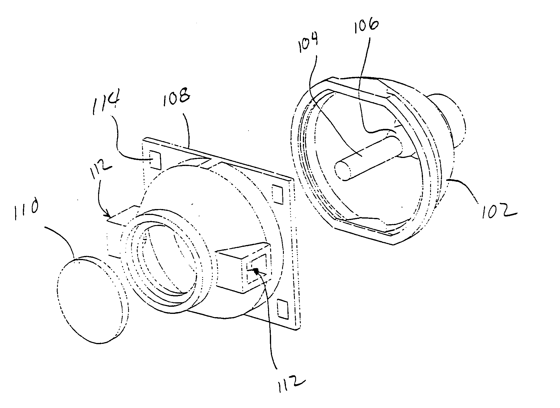
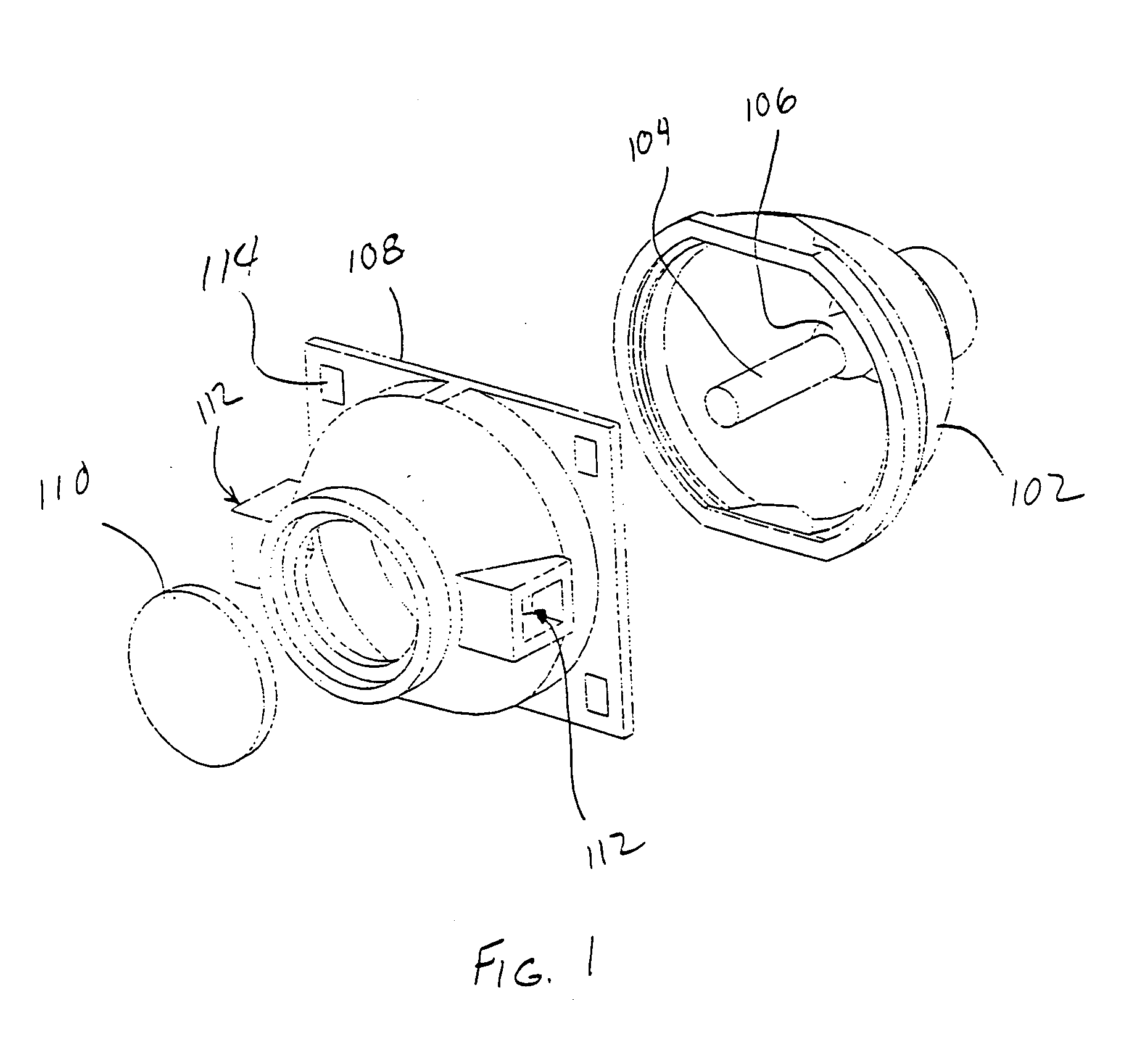
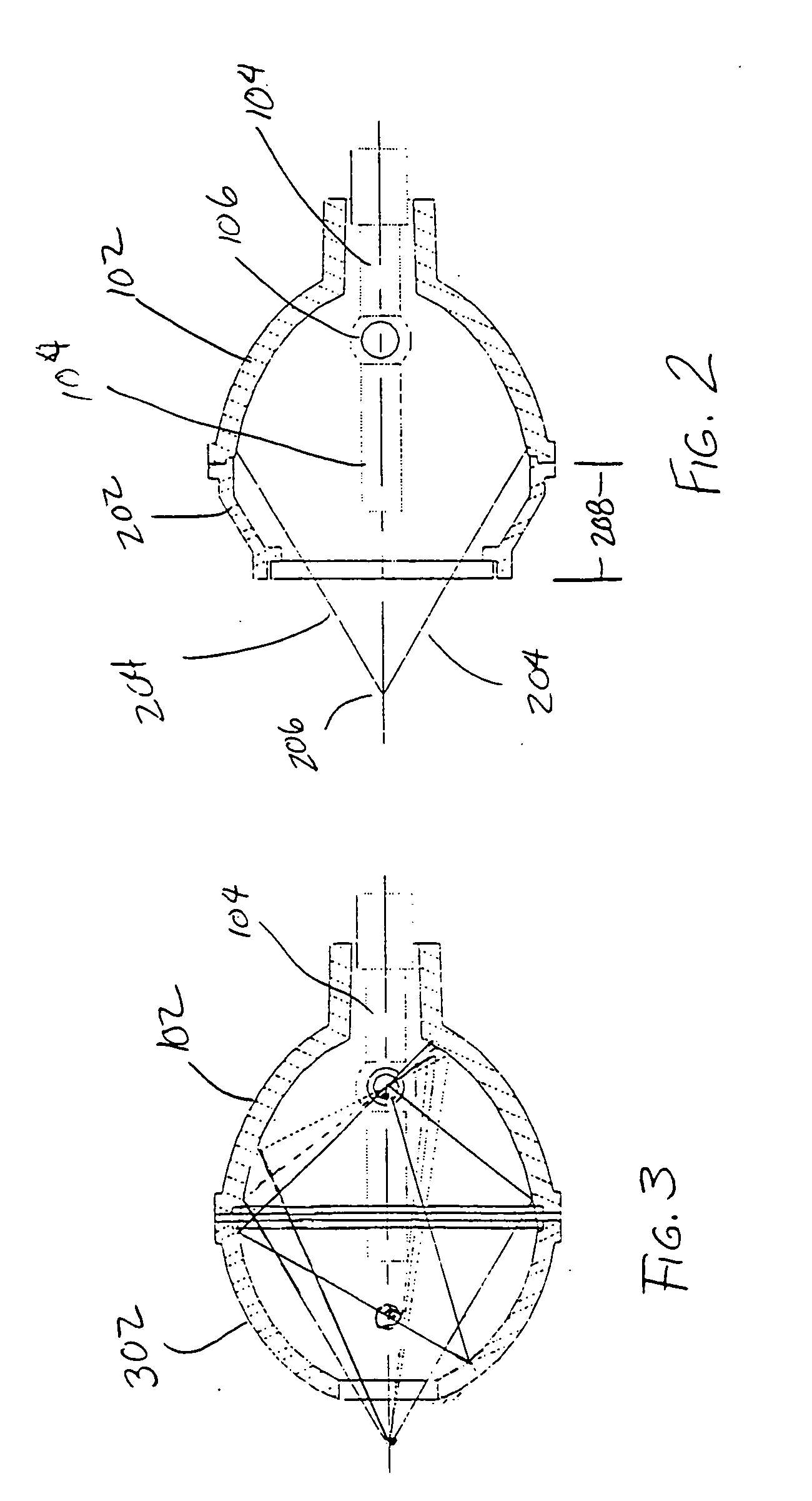
[0020]FIG. 1 is a cross section perspective view of a lamp assembly according to one embodiment of the present invention. In FIG. 1, a reflector 102 contains the lamp element, or burner 104. The burner has an electrode extending from each end and a chamber 106 in the middle in which the arc and plasma are contained. The reflector 102 typically is an ellipse, with the arc positioned at one foci of the ellipse. An elliptical reflector is preferred since it focuses the light from the arc without requiring a condenser lens.

[0021] A reflector extension 108 is designed to mate to the reflector 102. The reflector extension 108 has a first open end toward the reflector 102. The first open end typically is in contact with the reflector 102 to form a s...


PUM


Abstract

A lamp assembly having a reflector (102) holding a lamp element, or burner (104). The reflector (102) typically is an ellipse, with the burner arc positioned at one foci of the ellipse. A reflector extension (108) is designed to mate to the reflector (102). The reflector extension (108) has a first open end toward the reflector (102). The first open end typically is in contact with the reflector (102) to form a seal around the perimeter preventing glass shards from escaping between the reflector (102) and reflector extension (108). Preferably, the reflector extension (108) contacts the reflector (102) around the perimeter of the reflector (102). The second end of the reflector extension (108) also is open to allow the light from the arc to exit the reflector extension (108). A transparent plate (110) placed across this second open end prevents glass from leaving the reflector extension (108). The transparent plate (110) typically is glass, and may have an antireflective coating applied to the plate to limit the light reflected by the plate (110). Two or more ventilation ports (112) in the reflector extension (108) allow cooling airflow into the cavity around the burner (104). These ventilation ports alternatively are a series of small holes or slots in the reflector extension (108).

Description

FIELD OF THE INVENTION [0001] This invention relates to the field of display systems, more particularly to display systems using high pressure lamps, more particularly to reflectors and housings for high pressure lamps. BACKGROUND OF THE INVENTION [0002] Projection display systems have improved dramatically over the last decade. The color gamut and purity has improved at the same time remarkable improvements in resolution and image brightness have also been made. On top of these changes, the size, weight, and cost of the projectors have fallen dramatically. These improvements have led to entirely new markets for the projectors. For example, mobile professionals are now able to carry their own projectors to presentations to ensure compatibility between their portable computer and the display projector. These portable computers weigh less than three pounds, yet produce excellent images even in relatively bright environments. [0003] In spite of the very small size and weight of the sta...

Claims


Application Information

Patent Timeline
Patent Type & Authority Applications(United States)
IPC IPC(8): F21V7/00F21V29/00F21V29/505
CPCF21V7/0025F21V7/08F21V25/12F21V29/83G03B21/28F21V29/505F21V29/004G03B21/2026
Inventor DAVIS, MICHAEL T.TRISKA, CHRIS A.MCKINLEY, JOHN T.
Owner TEXAS INSTR INC
Why Eureka
Try Eureka