
Incremental redundancy transmission in a MIMO communication system

a communication system and redundancy transmission technology, applied in the field of communication, can solve the problems of packet decoding errors, excessive system resources expended to transmit data packets, and underutilized channel capacity

Active Publication Date: 2005-03-10
QUALCOMM INC
View PDF32 Cites 212 Cited by
  • Summary
  • Abstract
  • Description
  • Claims
  • Application Information

AI Technical Summary

Benefits of technology

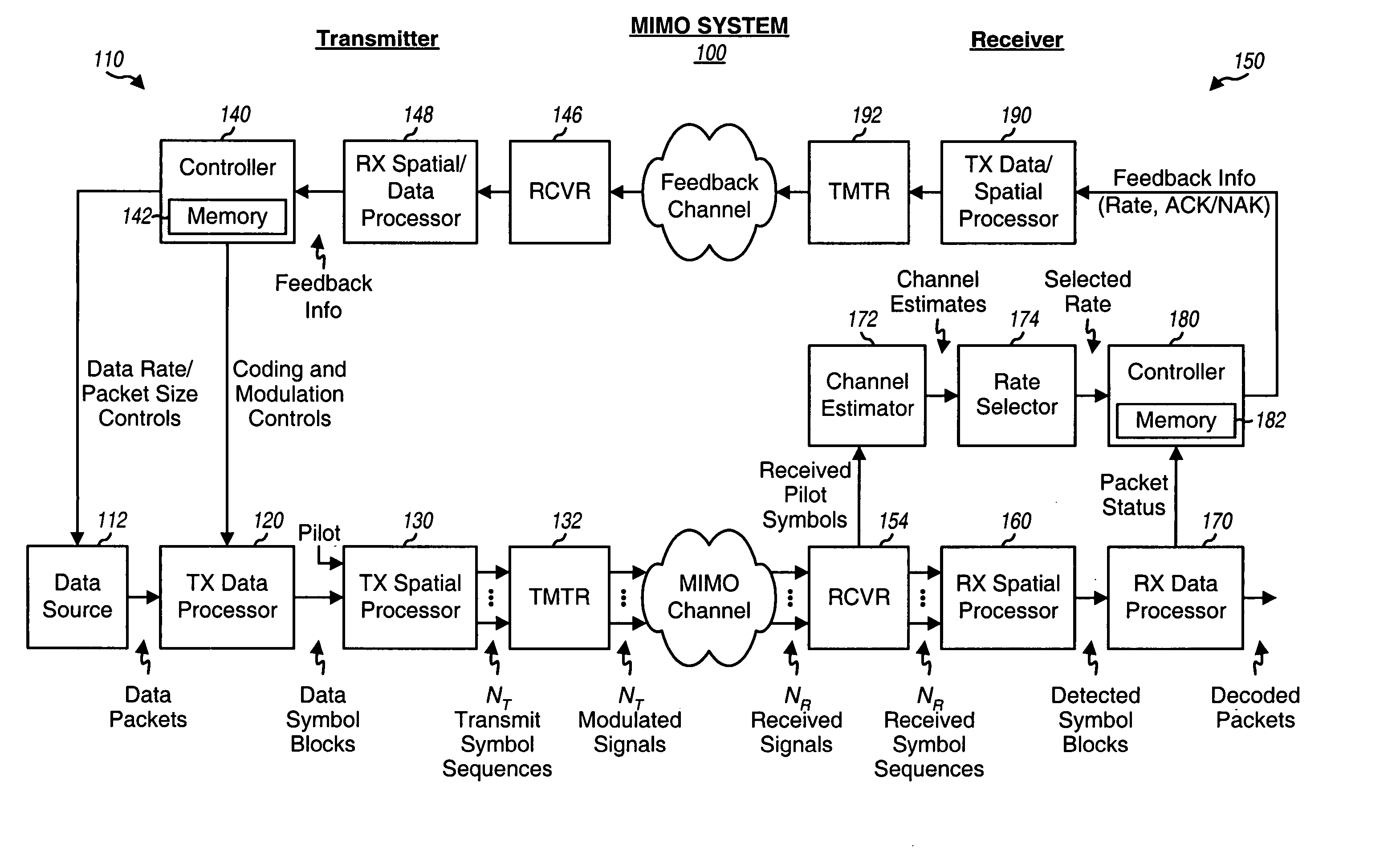
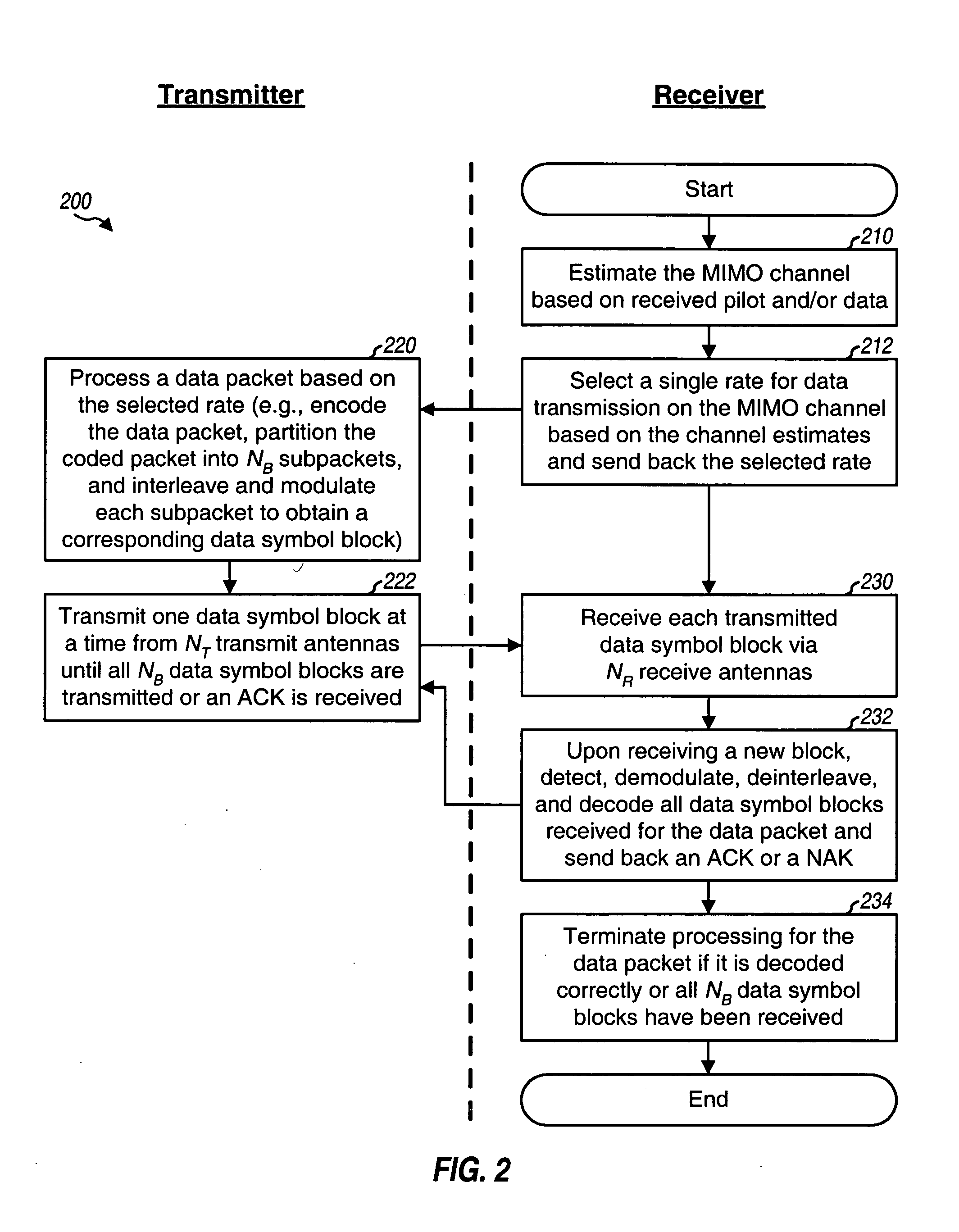
The transmitter processes (e.g., encodes, partitions, interleaves, and modulates) a data packet based on the selected rate and obtains multiple (NB) data symbol blocks for the data packet. The first data symbol block typically contains sufficient information to allow the receiver to recover the data packet under favorable channel conditions. Each of the remaining data symbol blocks contains additional redundancy

Problems solved by technology

A major challenge in a MIMO system is selecting a suitable rate for data transmission based on channel conditions.
If the selected rate for a data packet is too conservative (e.g., because the actual SNR is much better than the SNR estimate), then excessive system resources are expended to transmit the data packet and channel capacity is underutilized.
Conversely, if the selected rate for the data packet is too aggressive, then the packet may be decoded in error by the receiver and system resources may be expended to retransmit the data packet.
Rate selection for a MIMO system is challenging because of (1) greater complexity in the channel estimation for a MIMO channel and (2) the time-varying and independent nature of the multiple spatial channels of the MIMO channel.

Method used


Image

  • Incremental redundancy transmission in a MIMO communication system
  • Incremental redundancy transmission in a MIMO communication system
  • Incremental redundancy transmission in a MIMO communication system

Examples


Embodiment Construction

The word “exemplary” is used herein to mean “serving as an example, instance, or illustration.” Any embodiment or design described herein as “exemplary” is not necessarily to be construed as preferred or advantageous over other embodiments or designs.

For a MIMO system with NS spatial channels, NP data packets may be transmitted simultaneously from the NT transmit antennas, where 1≦NP≦NS. A single rate may be used for all data packets transmitted simultaneously, regardless of the value for NP. The use of a single rate can simplify the processing at both the transmitter and the receiver in the MIMO system.

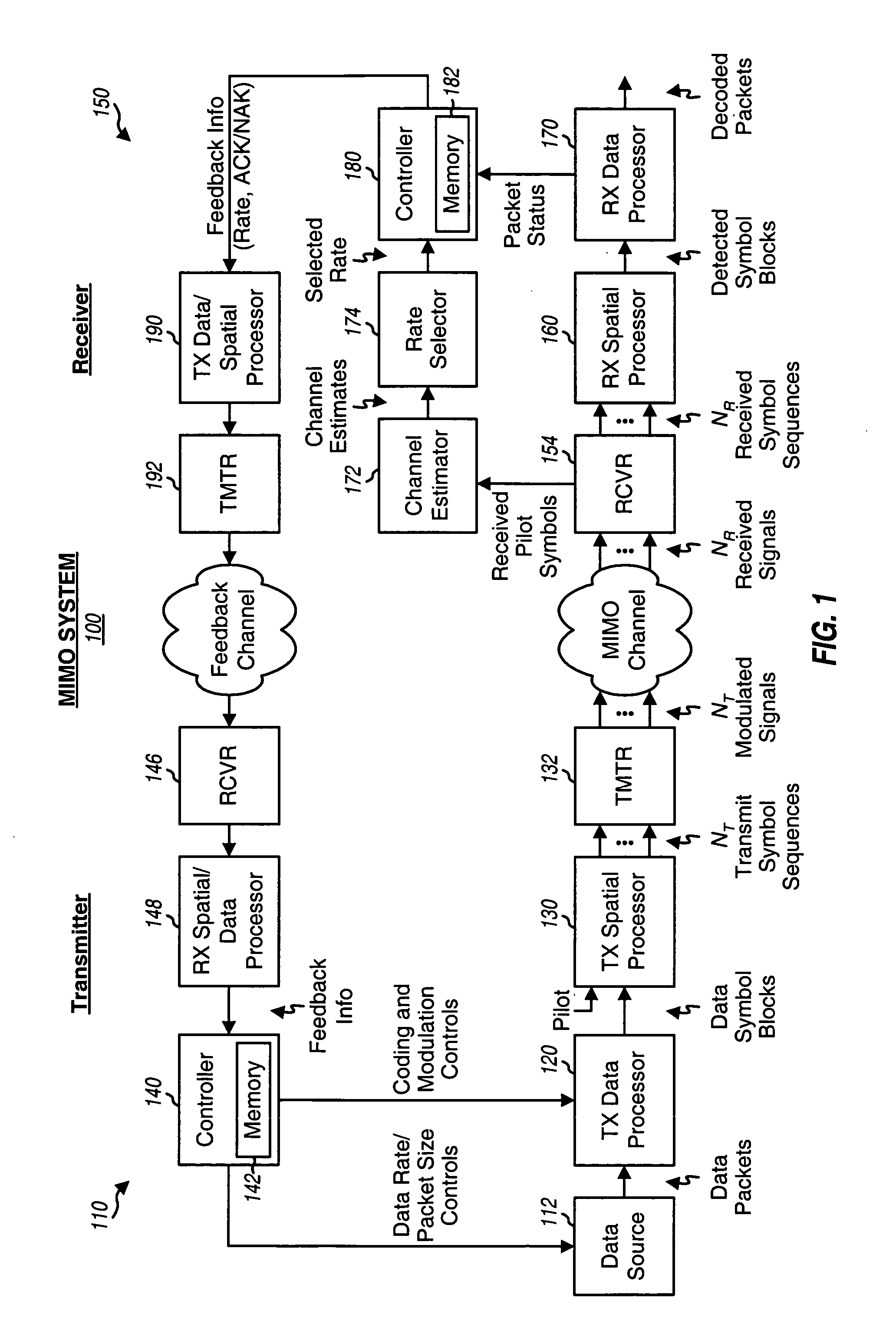
FIG. 1 shows a block diagram of a transmitter 110 and a receiver 150 in a MIMO system 100 that implements IR transmission. At transmitter 110, a TX data processor 120 receives data packets from a data source 112. TX data processor 120 processes (e.g., formats, encodes, partitions, interleaves, and modulates) each data packet in accordance with a rate selected for that packet to o...


PUM


Abstract

For an incremental redundancy (IR) transmission in a MIMO system, a transmitter processes (e.g., encodes, partitions, interleaves, and modulates) a data packet based on a selected rate to obtain multiple data symbol blocks. The transmitter transmits one data symbol block at a time until a receiver correctly recovers the data packet or all blocks are transmitted. Whenever a data symbol block is received from the transmitter, the receiver detects a received symbol block to obtain a detected symbol block, processes (e.g., demodulates, deinterleaves, re-assembles, and decodes) all detected symbol blocks obtained for the data packet, and provides a decoded packet. If the decoded packet is in error, then the receiver repeats the processing when another data symbol block is received for the data packet. The receiver may also perform iterative detection and decoding on the received symbol blocks for the data packet multiple times to obtain the decoded packet.

Description

BACKGROUND I. Field The present invention relates generally to communication, and more specifically to techniques for transmitting data in a multiple-input multiple-output (MIMO) communication system. II. Background A MIMO system employs multiple (NT) transmit antennas and multiple (NR) receive antennas for data transmission and is denoted as an (NT, NR) system. A MIMO channel formed by the NT transmit and NR receive antennas may be decomposed into NS spatial channels, where NS≦min {NT, NR}. The MIMO system can provide increased transmission capacity if the NS spatial channels created by the multiple transmit and receive antennas are used for data transmission. A major challenge in a MIMO system is selecting a suitable rate for data transmission based on channel conditions. A “rate” may indicate a particular data rate or information bit rate, a particular coding scheme, a particular modulation scheme, a particular data packet size, and so on. The goal of the rate selection is t...

Claims


Application Information

Patent Timeline
IPC IPC(8): H04LH04L1/00H04L1/06H04L1/16H04L1/18H04L12/26H04W16/28H04W28/04H04W28/18H04W28/22
CPCH03M13/33H04L1/0003H04L1/0009H04L1/0048H04L1/005H04L1/0071H04L27/2647H04L1/1671H04L1/1819H04L5/0023H04L5/0048H04L27/2626H04L1/0618H04B7/0417H04B7/0623
Inventor KADOUS, TAMER
Owner QUALCOMM INC
Learn More