
Transfer of packet data to wireless terminal

a wireless terminal and packet data technology, applied in data switching networks, store-and-forward switching systems, instruments, etc., can solve the problem of similar downlink packets of ggsn, and achieve the effect of reducing the functionality and resources required, and avoiding the processing of tft information elements in the mobile station

Active Publication Date: 2005-03-10
CONVERSANT WIRELESS LICENSING LTD
View PDF10 Cites 52 Cited by
  • Summary
  • Abstract
  • Description
  • Claims
  • Application Information

AI Technical Summary

Benefits of technology

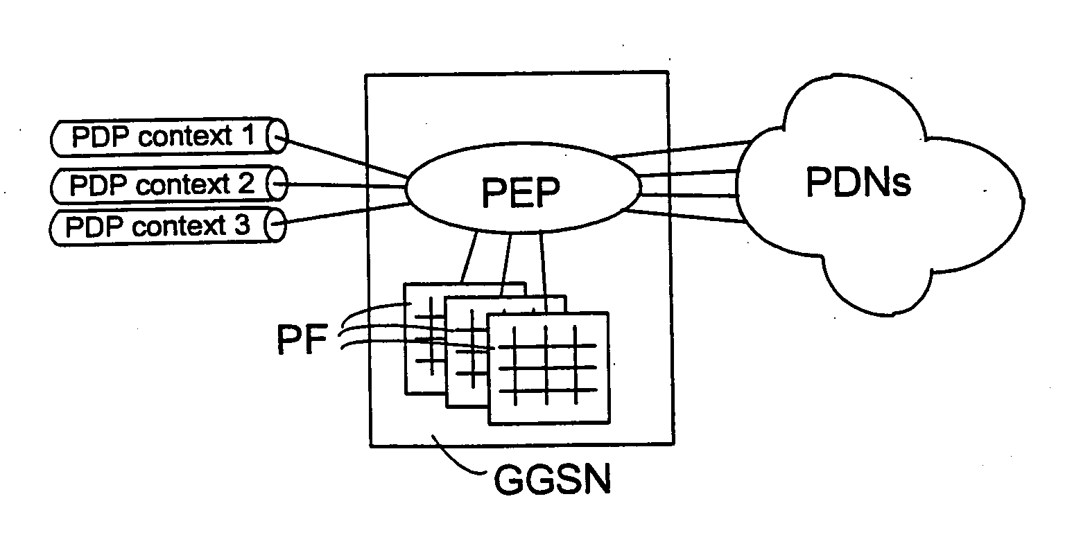
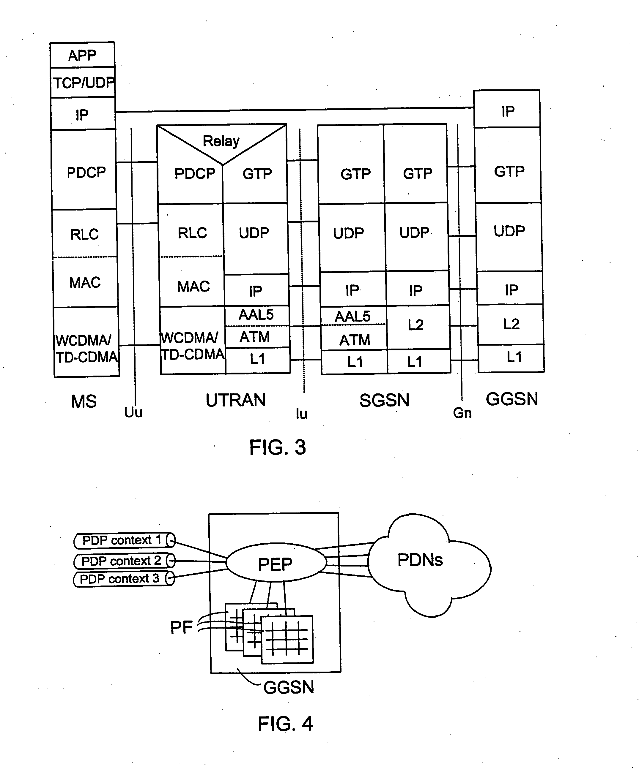
[0009] In accordance with a preferred embodiment of the invention, a UMTS system utilizing TFT information elements is concerned, whereby an identifier identifying the PDP context is transferred to a gateway GPRS support node PEP function constituting a gate formed by application-plane identifiers, wherein the identifier is associated with at least one filter. The PEP function may map the data flow fulfilling the filter parameters to a PDP context identified by the identifier, whereby the TFT filter is not needed at the gateway GPRS support node. In this case, the processing of TFT information elements in the mobile station can also be avoided, which reduces the functionality and resources required of the mobile station.

Problems solved by technology

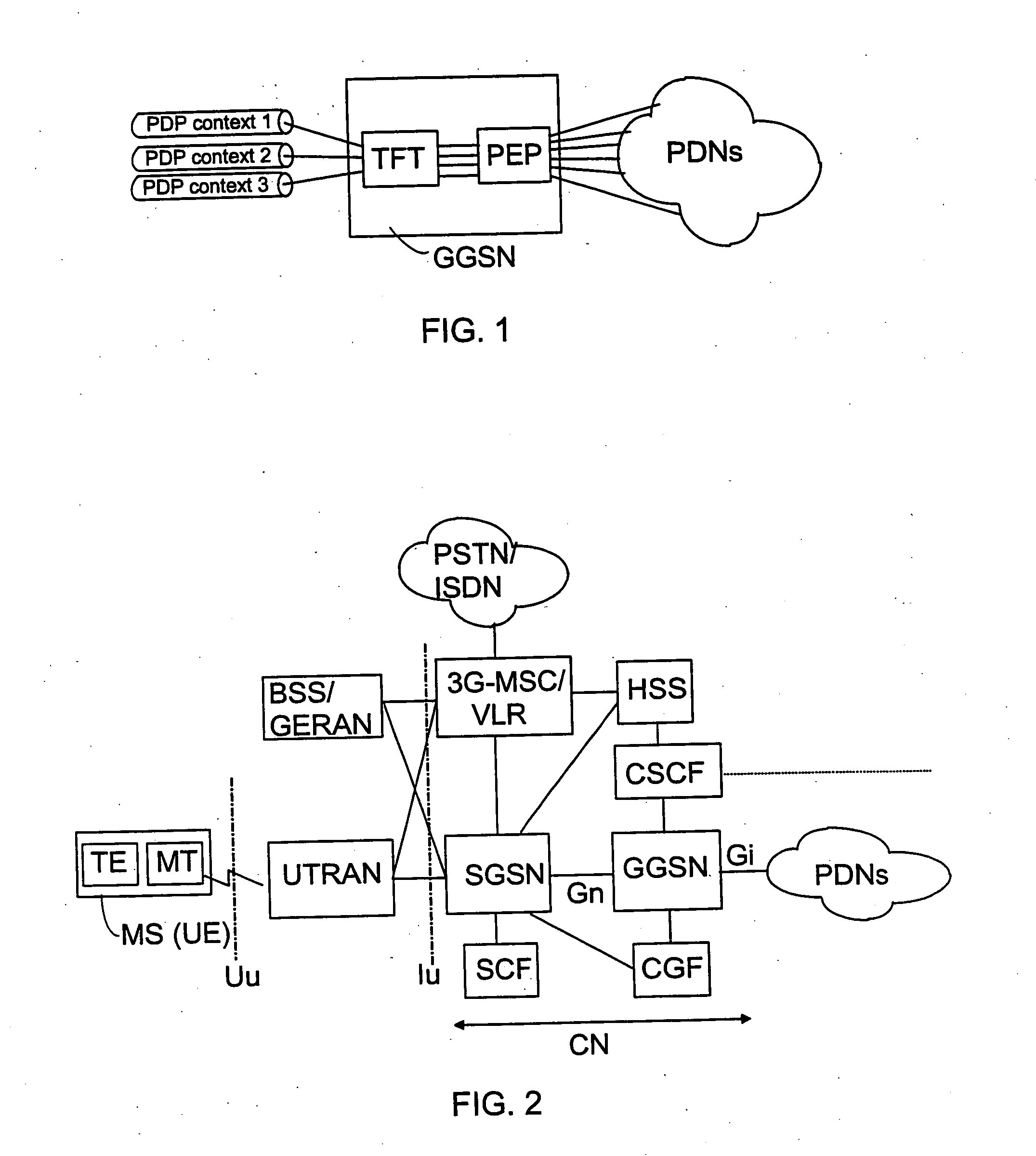
A problem in the above arrangement is that the GGSN performs similar downlink packet filtering by means of the gate functionality provided both by the TFT templates and by the PEP functionality.
Problems arise if these filters do not match, in which case the packets do not end up in the right PDP contexts.

Method used


Image

  • Transfer of packet data to wireless terminal
  • Transfer of packet data to wireless terminal
  • Transfer of packet data to wireless terminal

Examples


Embodiment Construction

[0017] The method of a preferred embodiment of the invention is described next in conjunction with an exemplary UMTS system. However, the invention is applicable to any packet-switched telecommunication system wherein data flows need to be mapped. The method of the invention is applicable to e.g. a second generation GPRS service (General Packet Radio Service).

[0018] Reference is made to FIG. 2, wherein the main parts of a mobile system include a core network CN and a UMTS terrestrial radio access network UTRAN, which constitute the fixed network of the mobile system, and a mobile station MS, also called user equipment UE. The interface between the CN and the UTRAN is called Iu, and the air interface between the UTRAN and the MS is called Uu.

[0019] The UTRAN is typically composed of several radio network subsystems RNS, the interface between which is called Iur (not shown). The RNS is composed of a radio network controller RNC and one or more base stations BS, for which the term no...


PUM


Abstract

The invention relates to transfer of packet data from a first subsystem via a network node in a second subsystem to a terminal in the second subsystem. The method includes negotiating identifiers identifying a data flow of the first subsystem via a separate signalling element during the set-up of an application-plane logical connection of the terminal. The identifiers are transmitted from the signalling element to the network node. In the method, a filter is generated at least on the basis of the identifiers for directing the mapping of at least one data flow of the first subsystem to at least one data flow of the second subsystem. The filter is bound to at least one data flow of the second subsystem, and at least one data flow of the first subsystem is mapped to at least one data flow of the second subsystem on the basis of the filter.

Description

BACKGROUND OF THE INVENTION [0001] The invention relates to the transfer of packet-switched data to a wireless terminal. [0002] PDP contexts (Packet Data Protocol) are used in the transfer of user data in GPRS services (General Packet Radio Service) and in packet-switched services of the UMTS system (Universal Mobile Telecommunications System). PDP contexts are generally logical connections, on which IP data are transferred from a mobile station to a boundary node (GGSN) in a UMTS network and vice versa. For the mobile station, a PDP address (at least one) is specified, for which several PDP contexts can be opened in the UMTS system. The first context is called a primary PDP context and the next PDP contexts are secondary PDP contexts. [0003] The mobile station knows which application data flows are to be directed to which links of a PDP context in uplink data transfer. In downlink, the gateway GPRS support node should also know packet-specifically which PDP context is used for each...

Claims


Application Information

Patent Timeline
IPC IPC(8): H04L12/54H04W76/02H04W76/04H04W92/02
CPCH04L12/5695H04L47/10H04L47/14H04L47/2491H04W92/02H04L47/786H04L47/824H04W76/021H04W76/022H04L47/765H04L47/70H04W76/12H04W76/11H04W28/02H04W28/10H04W8/04
Inventor JOUPPI, JARKKO
Owner CONVERSANT WIRELESS LICENSING LTD
Learn More