

Digital watermark detection method and apparatus
a detection method and digital technology, applied in the field of digital watermark detection methods and apparatuses, can solve the problems of increasing the arithmetic operation volume and circuit scale, the inability to detect watermarks, and the danger of unrestricted formation of copies of digital images, so as to achieve accurate detection of watermark information, the effect of reducing the amount of operation and circuit scal
- Summary
- Abstract
- Description
- Claims
- Application Information
AI Technical Summary
Benefits of technology
Problems solved by technology
Method used
Image

Examples
first embodiment
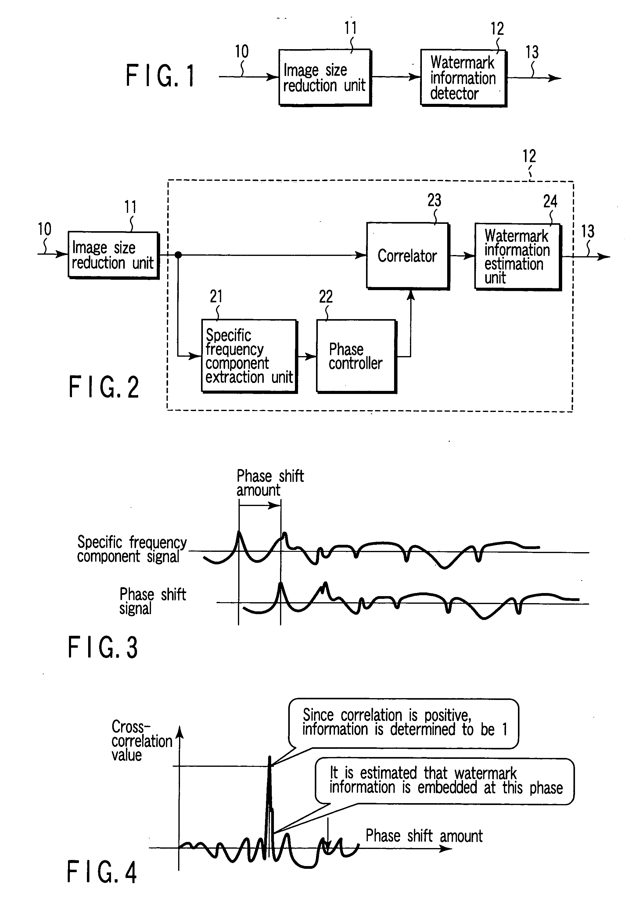
(First Embodiment)
In the most basic digital watermark detection apparatus shown in FIG. 1 according to a first embodiment of the invention, an input image signal 10 having watermark information embedded therein is input to an image size reduction unit 11. The image size reduction unit 11 reduces the size of an image corresponding to the input image signal 10 (i.e., reduces the size of image data contained in the input image signal). The image size is generally defined by (number of pixels in the horizontal direction×number of pixels in the vertical direction) of an image. Accordingly, the image size reduction unit 11 reduces the resolution of an image for size reduction, thereby generating a size-reduced image signal of a reduced resolution.
The size-reduced image signal generated by the image size reduction unit 11 is input to a watermark information detector 12, which, in turn, detects digital watermark information in the signal. The method for detecting digital watermark inform...
second embodiment
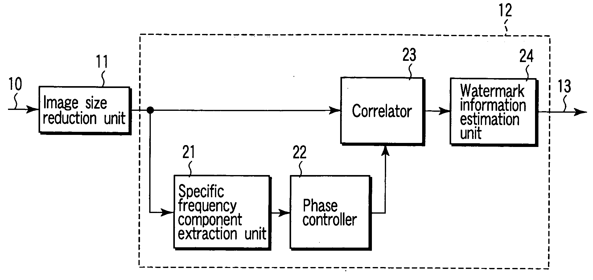
(Second Embodiment)
In the second embodiment shown in FIG. 2, a size-reduced image signal from the image size reduction unit 11 is input to the input of a specific frequency component extraction unit 21 and the first input of a correlator 23, which are incorporated in the watermark information detector 12.
The watermark information detector 12 comprises the specific frequency component extraction unit 21, phase controller 22, correlator 23 and watermark information estimation unit 24. The specific frequency component extraction unit 21 is formed of a digital filter of the same frequency band as that of a specific frequency component extraction unit incorporated in the aforementioned digital watermark embedding apparatus.
More specifically, the unit 21 is formed of an HPF (High Pass Filter) having a specific cutoff frequency, or a BPF (Band Pass Filter) having a passband center frequency. The specific frequency component extraction unit 21 extracts a specific frequency component, s...
third embodiment
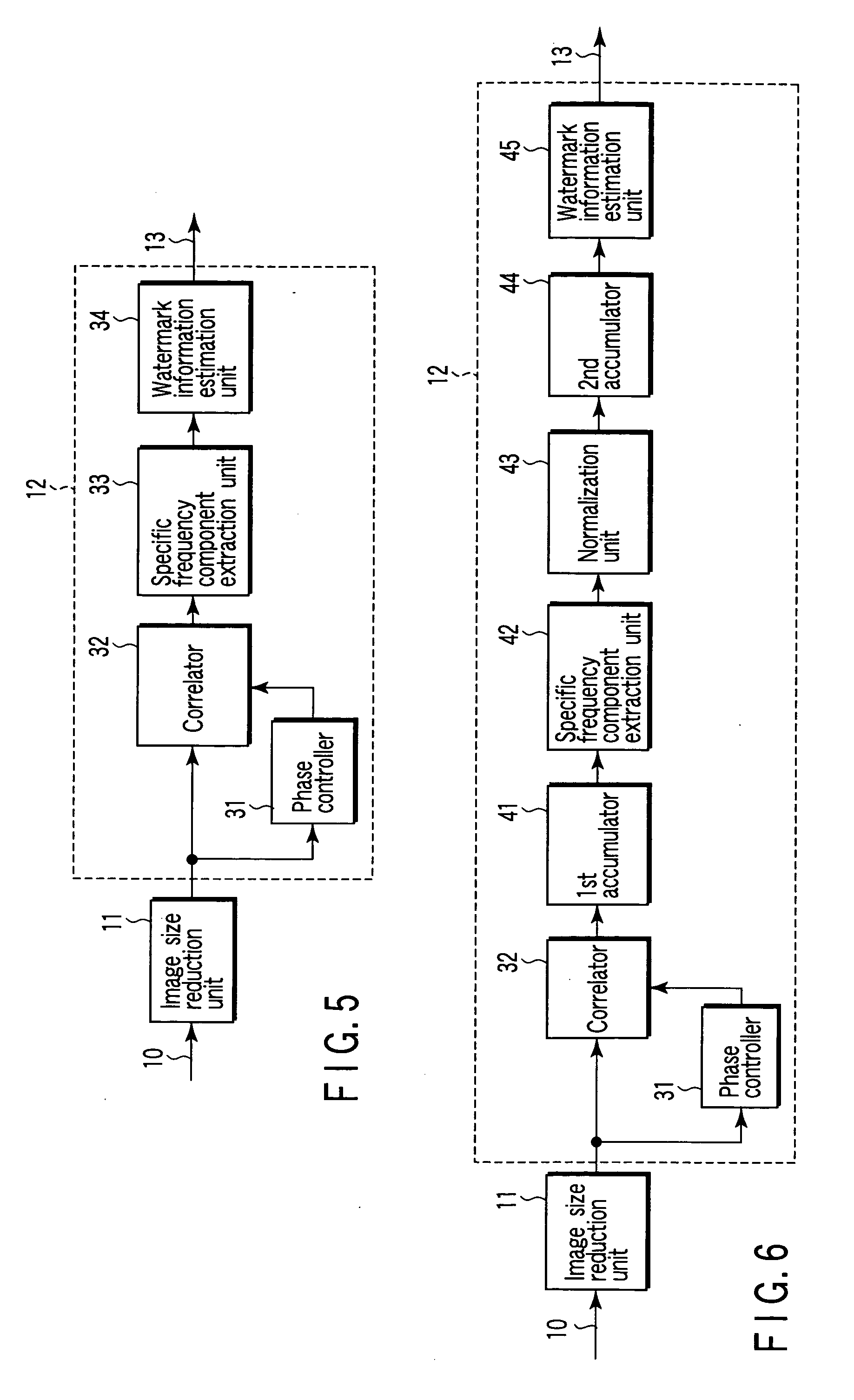
(Third Embodiment)
In the third embodiment shown in FIG. 5, a size-reduced image signal from the image size reduction unit 11 is input to the input of a specific frequency component extraction unit 31 and the first input of a correlator 32. The size-reduced image signal having its phase controlled by the phase controller 31 is input to the second input of the correlator 32. The correlator 32 performs correlation between the signals input to its first and second inputs, thereby generating an auto-correlation function. This auto-correlation function is input to a specific frequency component extraction unit 33.
The specific frequency component extraction unit 33 comprises an HPF or a BPF, as in the specific frequency component extraction unit 21 shown in FIG. 2, and extracts a specific frequency component by filtering the auto-correlation function. The extracted specific frequency component signal is input to a watermark information estimation unit 34, where the peak level of the ext...
PUM
| Property | Measurement | Unit |
|---|---|---|
| time | aaaaa | aaaaa |
| time | aaaaa | aaaaa |
| time | aaaaa | aaaaa |
Abstract
Description
Claims
Application Information