Functional spinal unit prosthetic

Inactive Publication Date: 2005-03-10
DEPUY SPINE INC (US)
View PDF29 Cites 422 Cited by
  • Summary
  • Abstract
  • Description
  • Claims
  • Application Information

AI Technical Summary

Benefits of technology

Also, the present invention, in a second part, replaces the natural facet joint capsule with an artificial construct that more fully provides the natural mechanical relationship provided by a natural healthy facet joint. In particular, by providi

Problems solved by technology

Replacing the articular surface may relieve pain

Method used


Image

  • Functional spinal unit prosthetic
  • Functional spinal unit prosthetic
  • Functional spinal unit prosthetic

Examples


example i

This prophetic example will demonstrate one method of implanting the components of the present invention:

In some embodiments, the motion disc is implanted in substantial accordance with the methods described in U.S. Provisional Application US Ser. No. 60 / 459,280, Hawkins et al., filed Mar. 31, 2004, entitled “Method and Apparatus for Disc Insertion”, Attorney Docket No. 3518.100-001, the specification of which is incorporated by reference in its entirety

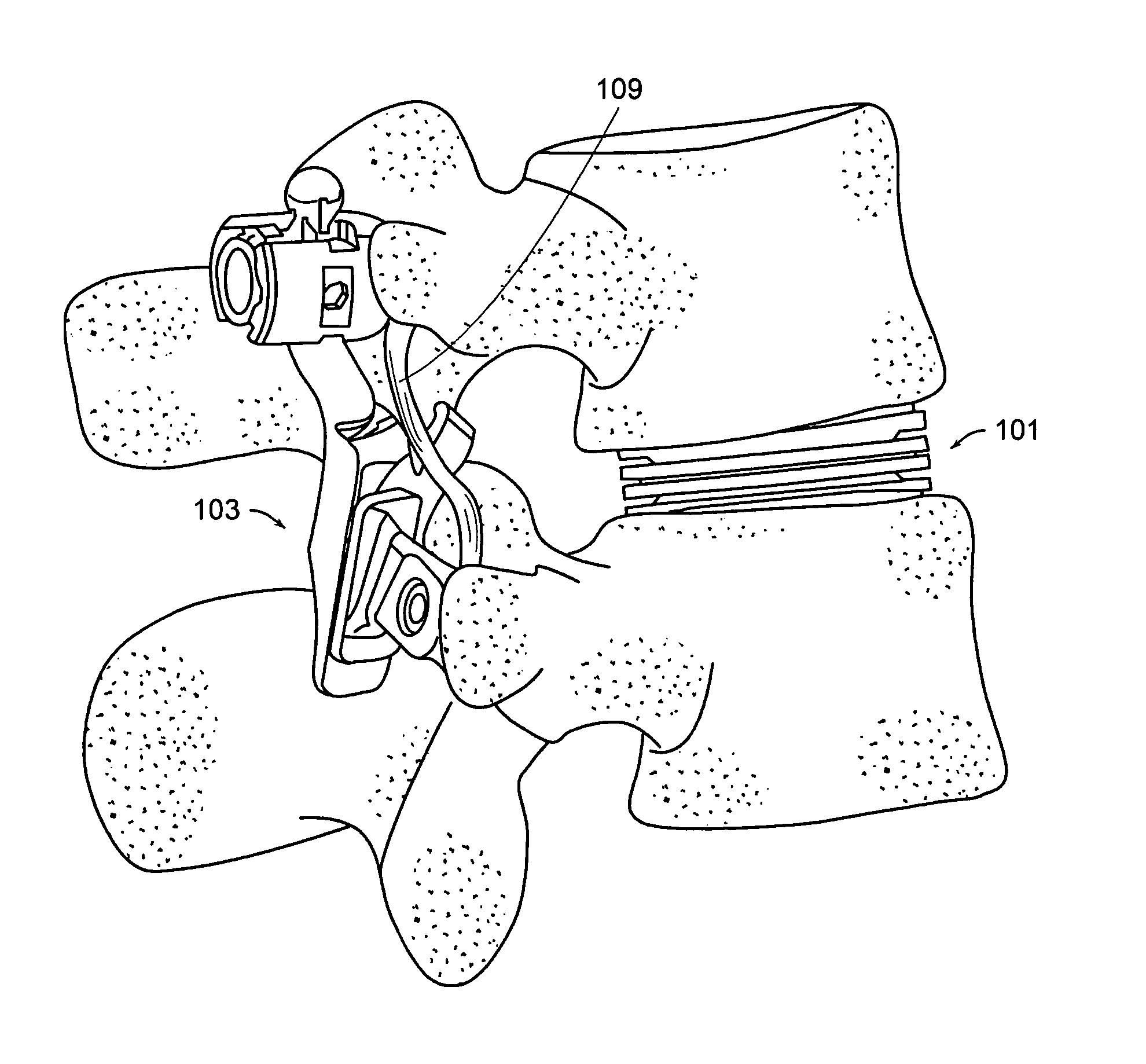
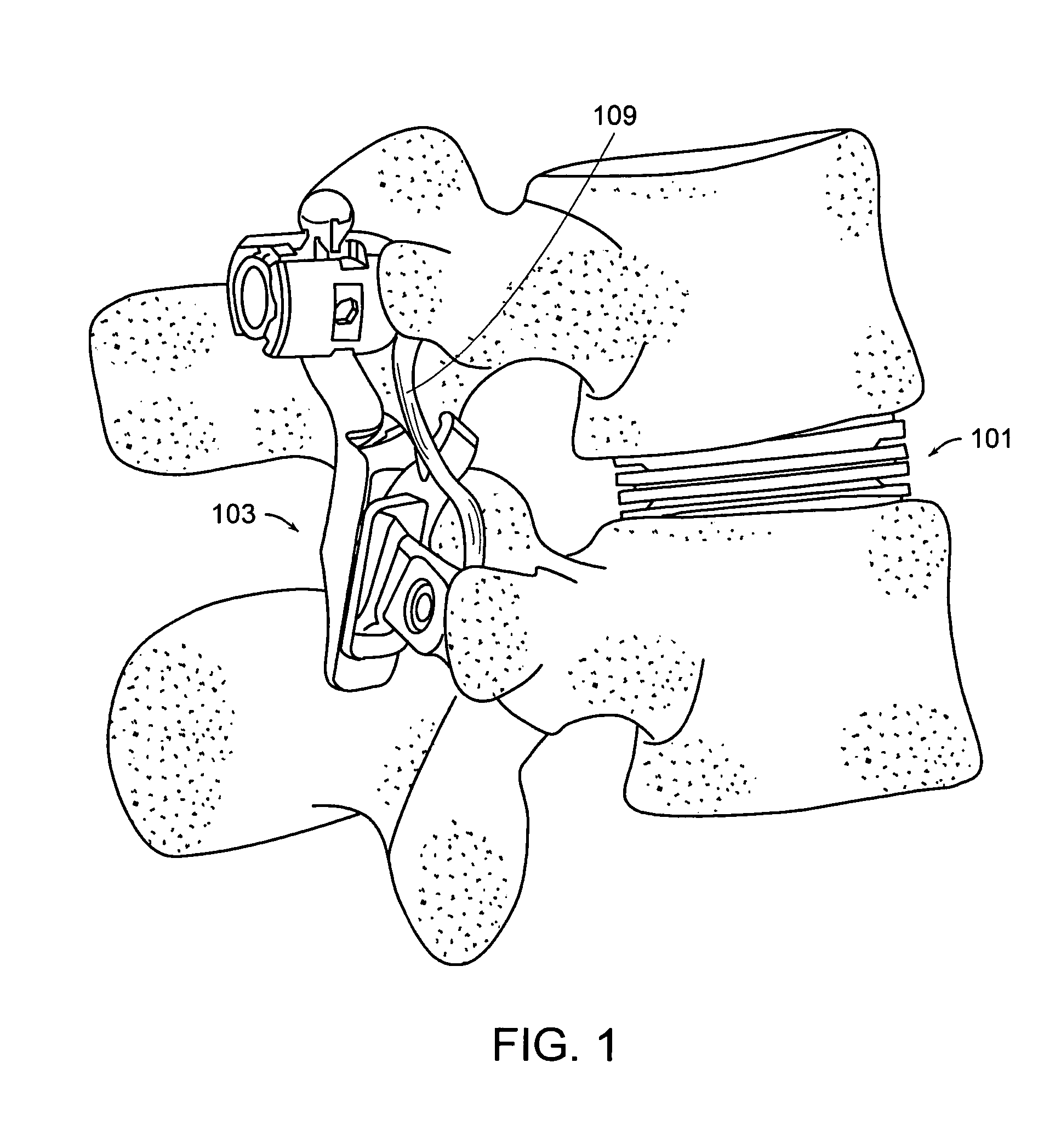
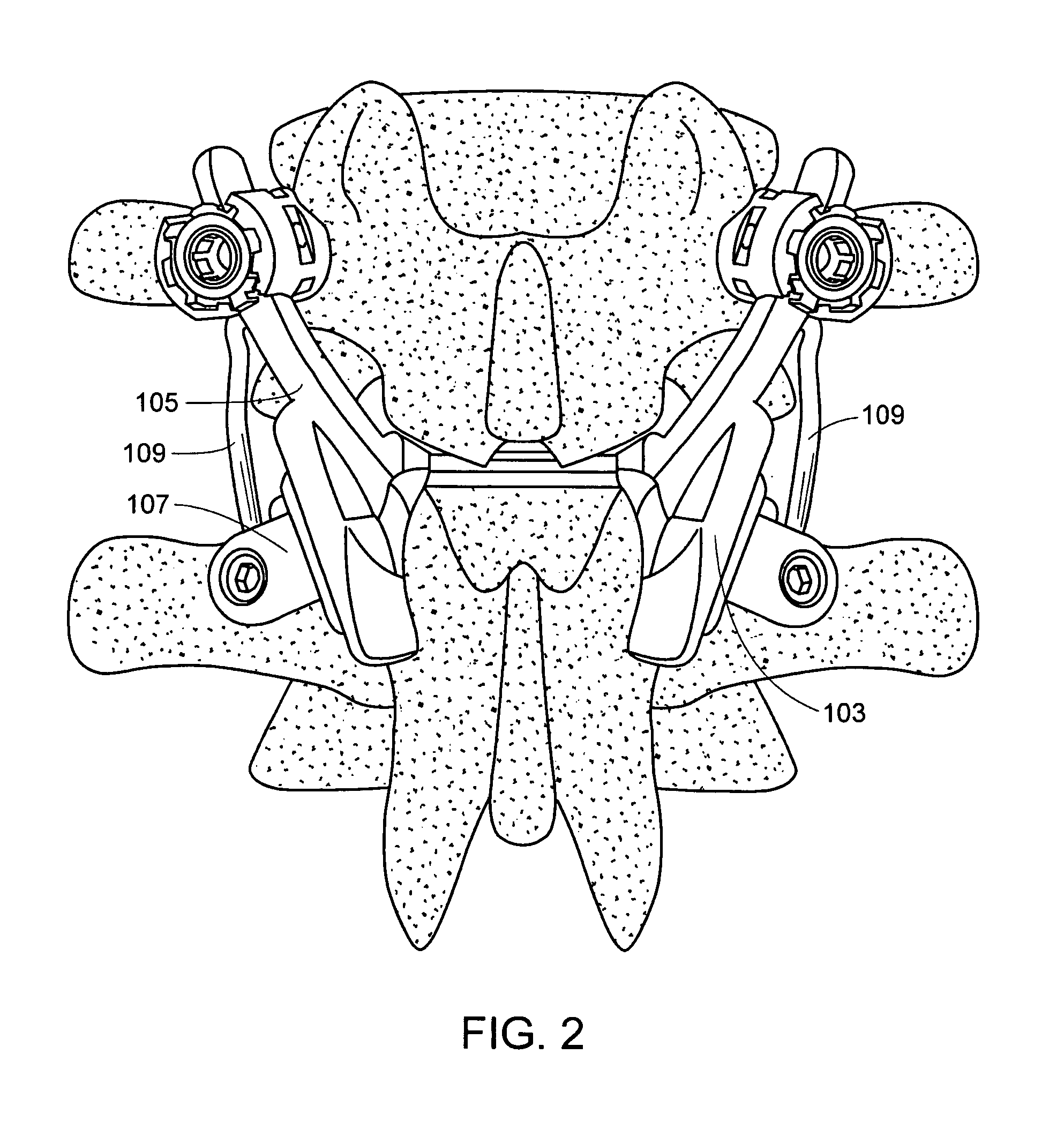
First, the surgeon uses a standard posterior approach (either bilateral or unilateral) to uncover the facet joint. Next, the surgeon resects (excises) the facet processes, using standard resection instruments, such as a rongeur or a curette.

Next, the surgeon prepares the surface of each pedicle for insertion of a pedicle screw. This entails locating the appropriate trajectory, probing the pilot hole, and preparing the pedicle surface to receiving the screw.

Next, the surgeon implants the superior pedicle screw into the superi...


PUM

PropertyMeasurementUnit
Shapeaaaaaaaaaa

Abstract

A facet joint replacement system having an elongate rod and a polyaxial screw having a groove therein, wherein the rod is slidably received within the groove of the polyaxial screw.

Description

BACKGROUND OF THE INVENTION One of the most common surgical interventions today is arthrodesis, or spine fusion, in which two or more adjacent vertebral bodies are fused together in order to alleviate pain associated with the disc(s) located between those vertebral bodies. Approximately 300,000 such procedures are performed annually in the United States alone. Clinical success varies considerably, depending upon technique and indications, and consideration must be given to the concomitant risks and complications. While spine fusion generally helps to eliminate certain types of pain, it has also been shown to decrease function by limiting the range of motion for patients in flexion, extension, rotation and lateral bending. Furthermore, it is believed that spine fusion creates increased stresses on (and, therefore, accelerated degeneration of) adjacent non-fused motion segments. Additionally, pseudoarthrosis, resulting from an incomplete or ineffective fusion, may reduce or even tot...

Claims


Application Information

Patent Timeline
IPC IPC(8): A61B17/04A61B17/70A61F2/00A61F2/02A61F2/08A61F2/30A61F2/44
CPCA61B17/0401A61F2310/00976A61B17/7064A61F2/08A61F2/30A61F2/30742A61F2/30965A61F2/4405A61F2/442A61F2/4425A61F2/4455A61F2002/30014A61F2002/30032A61F2002/30062A61F2002/30224A61F2002/30242A61F2002/30383A61F2002/30462A61F2002/30507A61F2002/30553A61F2002/30563A61F2002/30565A61F2002/30578A61F2002/30649A61F2002/30662A61F2002/30673A61F2002/30682A61F2002/30772A61F2002/30774A61F2002/30777A61F2002/30841A61F2002/443A61F2210/0004A61F2220/0025A61F2220/0075A61F2230/0069A61F2230/0071A61F2250/0008A61F2250/0018A61F2250/003A61F2310/00011A61F2310/00017A61F2310/00023A61F2310/00029A61F2310/00161A61F2310/00179A61F2310/00365A61F2310/00796A61B17/7011
Inventor SERHAN, HASSAN A.LABROM, ROBERTHAWKINS, JOHN R.DUNBAR, WILLIAMBORGSTROM, AMIEKWAK, SEUNGKYU DANIELDOORIS, ANDREWSLIVKA, MICHAEL A.
Owner DEPUY SPINE INC (US)
Why Eureka
Try Eureka