Method and apparatus for providing distributed control of a home automation and control system

a control system and home automation technology, applied in the field of home automation and control systems, can solve the problems of limited approach, and inability to provide flexibility to the method, and achieve the effect of reducing network traffic and reducing delay

Inactive Publication Date: 2005-03-10
MICROSOFT TECH LICENSING LLC
View PDF16 Cites 38 Cited by
  • Summary
  • Abstract
  • Description
  • Claims
  • Application Information

AI Technical Summary

Benefits of technology

[0016] Another benefit of the invention is a reduction in the network traffic required to launch a complex scene as compared to central controller prior art solutions. Only a single trigger message with the scene identifier must be sent to devices participating in a scene in order to launch the scene. There is no requirement for a central controller to send a “set device” command to each different scene member, group, or zone. No other message traffic is necessary. Each device maintains its own scene definition for each scene describing the state of the device for the scene. Therefore, the launch scene command only needs to identify the scene to system devices in order for the scene to be launched. This message protocol allows scene control to be distributed throughout the home automation and control system, and also reduces the delay found in current central-controller-based home automation and control systems between the time a trigger event is received and when the last scene member is activated.

Problems solved by technology

Current home automation and control systems are based on controlling devices through device resources, but these device resources are not interoperable between unlike resources.
Current home automation and control systems create and launch scenes using several methods, each of which has significant drawbacks.
This method does not provide the flexibility that in one scene some of the same type devices might be on and others off, while in another scene all of the devices might be on.
Such an approach is, thus, limited to simple, synchronized scenes.
If the central controller fails, scenes can no longer be triggered because the controller can no longer send the necessary messages to the scene member devices to produce the scenes.
In effect, if the central controller fails, the entire home automation and control system is rendered unusable.
This single point of failure is highly undesirable to users of such systems.
Additionally, the use of a central controller creates a heavy load of network traffic, since the central controller must send a message to each scene member device individually.
For a scene with a large number of devices, this also causes a time delay time between the start of the scene when the first device gets its message until the last device gets its message.
Such heavy network traffic and delay in triggering scene member devices is also undesirable to users of home automation and control systems.
If the manufacturer defined home mode does not entirely produce the scene state desired by the home user, or different states are desired for the same device types (a night scene has all lights out except a nightlight in the bathroom, as an example) the scene can not be modified.
Furthermore, such home automation and control systems can have only one active home mode at a time, and the home mode affects all devices in the system.
This is not desirable in a house with multiple users, where each user may want to select a different scene to control the user's local environment at the same time, without affecting any system devices not in the scene desired by the user.
However, the central programming tool may or may not be a permanent part of such a home automation and control system; and if the central programming tool is lost or fails, the system cannot be reconfigured.
This can be a problem when the user of the home automation and control system wishes to reconfigure the system, particularly when a new home owner finds the central programming tool went with the previous owner's computer or has otherwise been lost.
Also, the central programming tool is typically specialized, in that it is limited to device types that were known or contemplated when the original home automation and control system was installed.
Thus, the central programming tool cannot reconfigure the system to incorporate newly developed device types, such as new media players, environmental control devices, etc., for which the programming tool does not have the requisite programming instructions.
Furthermore, the addition of devices, whether originally contemplated or not, may reach a number exceeding the central programming tool or central controller limitations for number of devices in a scene.

Method used


Image

  • Method and apparatus for providing distributed control of a home automation and control system
  • Method and apparatus for providing distributed control of a home automation and control system
  • Method and apparatus for providing distributed control of a home automation and control system

Examples


Embodiment Construction

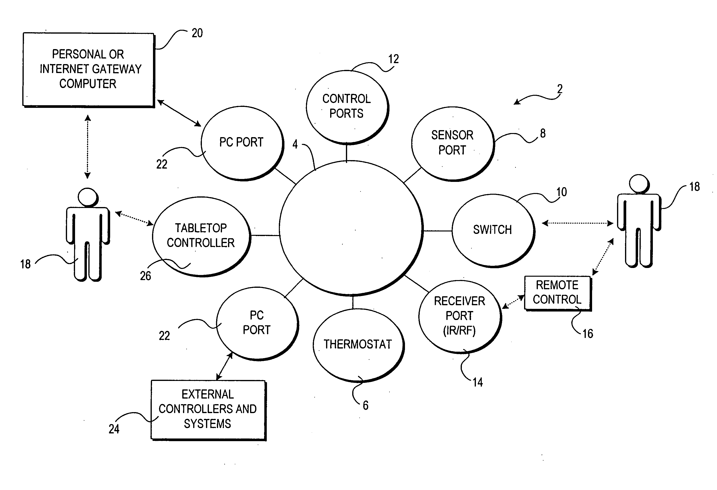
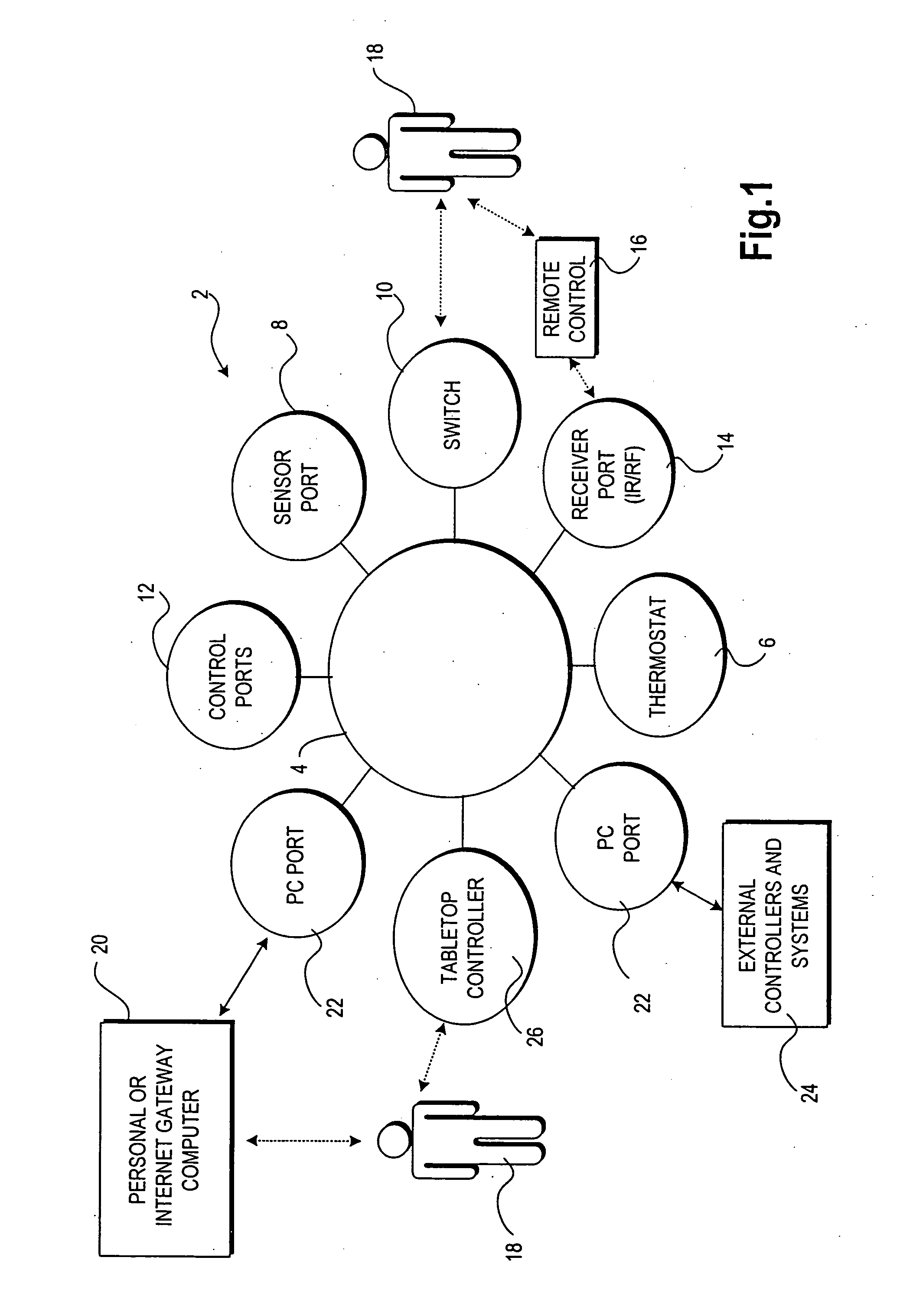
[0032] The present invention is directed to a method and apparatus for providing distributed scene programming and distributed control of a home automation and control system. According to an embodiment of the present invention, a device is provided for use in a home automation and control system that includes control logic for local storage of its house scene participation states. When multiple such devices are utilized throughout a home automation and control system, control of the system is distributed among the devices. Referring now to the figures, in which like numerals represent like elements, an actual embodiment of the present invention will be described. FIG. 1 provides an overview of an illustrative home automation and control system 2 in which aspects of the present invention may be practiced. It should be appreciated that the use of the term “home automation and control” includes, but is not limited to, home automation, home control, home networking, or connected home s...


PUM


Abstract

A method and apparatus for providing distributed control of a home automation and control system is provided. Each device participating in a home automation and control system is equipped with control logic for providing distributed control. Through the control logic, each device maintains scene definitions describing the state of the device for each scene in which it participates. When any device in the system receives a request to launch a scene, such as a button press on one of the devices, the device broadcasts a scene state change message to all devices within the home automation and control system. The scene state change message identifies to each device that a particular scene that should be launched. Each device in the system receives the message and determines whether the device is a participant in the scene. If the device is a participant in the scene, the device adjusts its state according to a scene definition stored in the device associated with the scene. The device may adjust a controlled electrical load, such as a light, according to the scene definition by turning the load on, off, or setting the load to some intermediate value. If the device is a not participant in the scene, the device remains unaffected.

Description

CROSS-REFERENCES TO RELATED APPLICATIONS [0001] This application is a continuation of U.S. patent application Ser. No. 10 / 154,425, filed May 22, 2002, which is a continuation-in-part of U.S. patent application Ser. No. 09 / 955,570, filed Sep. 17, 2001, which is a continuation of U.S. patent application Ser. No. 09 / 751,383, filed Dec. 29, 2000, now abandoned, which claims the benefit of prior U.S. Provisional Patent Application No. 60 / 173,741, filed Dec. 30, 1999, each of which applications is expressly incorporated herein by reference.FIELD OF THE INVENTION [0002] The present invention relates to the field of home automation and control systems and, more particularly, to a method and apparatus for providing distributed control of dynamically created home automation and control system scenes. BACKGROUND OF THE INVENTION [0003] Home automation and control systems are used to control the behavior of an environment such as a home or office building. Home automation and control systems al...

Claims


Application Information

Patent Timeline
Patent Type & Authority Applications(United States)
IPC IPC(8): H04L12/28
CPCH04L12/2803H04L12/2814H04L2012/285H04L12/2823H04L12/282G05B15/02G05B2219/25218G05B2219/25232G05B2219/2642G05B19/42G05B11/01G05B19/042
Inventor GONZALES, GREGBAKER, BRIAN D.WHITE, SARA
Owner MICROSOFT TECH LICENSING LLC
Why Eureka
Try Eureka