
Instrumentation for resource management architecture and corresponding programs therefor

a resource management and instrumentation technology, applied in instruments, multi-programming arrangements, data switching networks, etc., can solve the problems of a monstrous supercomputer, a large amount of computer power, and no data analysis very deeply for weak signals

Active Publication Date: 2005-03-10
THE UNITED STATES OF AMERICA AS REPRESENTED BY THE SECRETARY OF THE NAVY
View PDF5 Cites 122 Cited by
  • Summary
  • Abstract
  • Description
  • Claims
  • Application Information

AI Technical Summary

Benefits of technology

FIGS. 13A, 13B, and 13C are block diagrams which are useful in explaining various operational and functional aspects of the Resource Management Architecture according to the present invention; and
FIG. 14 is a high-level block diagram illustrating connectivity and data flow between the Hardware Broker and the other Resource Management and Resource Management-related functional elements in the Resource Management Architecture; and
FIG. 15 is a high-level block diagram of a CPU-based general computer which can act as a host in the Resource Management Architecture according to the present invention.

Problems solved by technology

None of these computers look very deeply at the data for weak signals nor do they look for a large class of signal types.
The reason for this is because they are limited by the amount of computer power available for data analysis.
To extract the weakest signals, a great amount of computer power is necessary.
It would take a monstrous supercomputer to get the job done.
Moreover, SETI programs could never afford to build or buy that computing power.
It will be appreciated that these approaches to computing in a distributed environment do not provide a system that is both flexible and adaptive (or at least easily adapted) to changes in system configuration, performance bottlenecks, survivability requirements, scalability, etc.

Method used


Image

  • Instrumentation for resource management architecture and corresponding programs therefor
  • Instrumentation for resource management architecture and corresponding programs therefor
  • Instrumentation for resource management architecture and corresponding programs therefor

Examples


Embodiment Construction

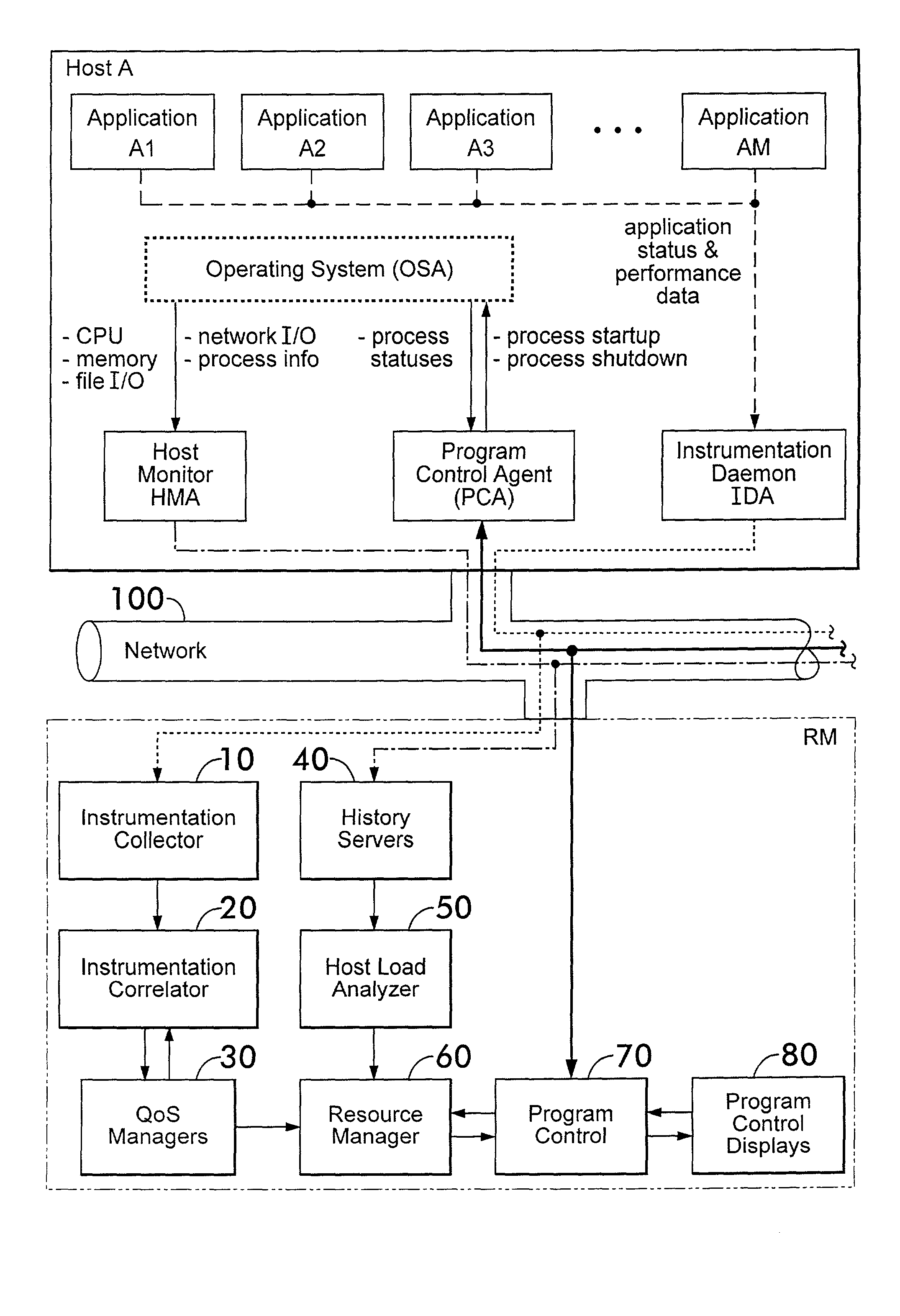
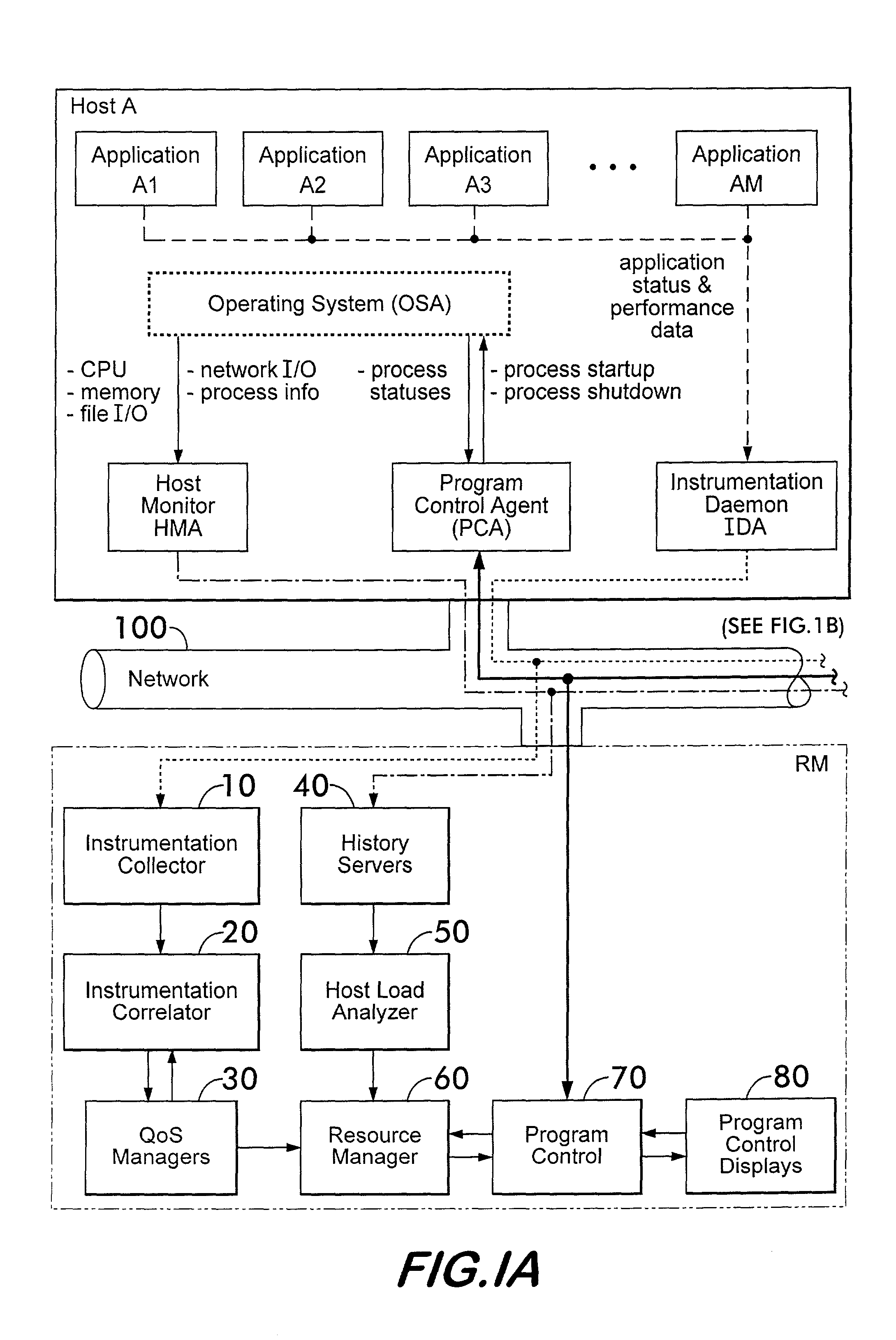
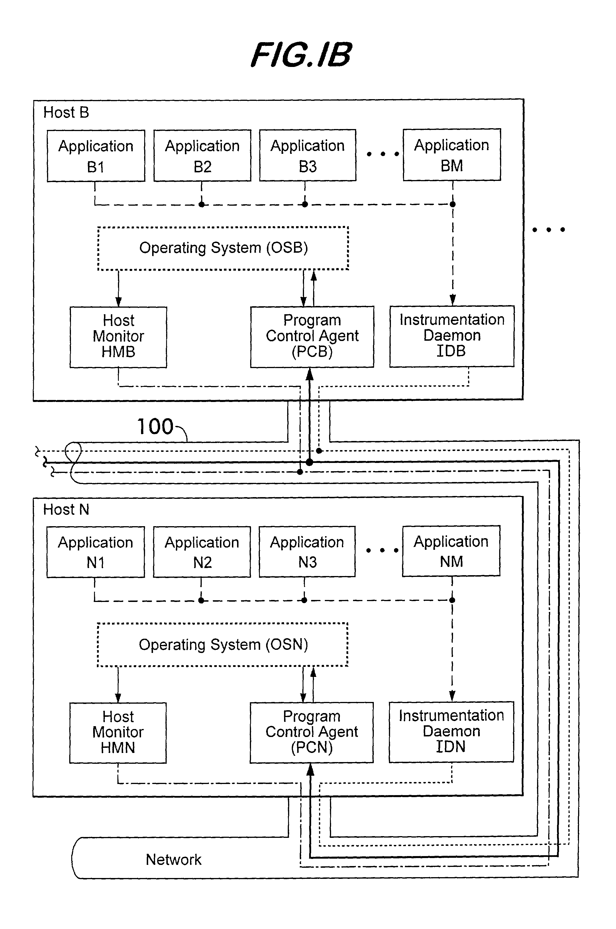
The Resource Management Architecture, which was and is being developed by the Naval Surface Warfare Center—Dahlgren Division (NSWC-DD), provides capabilities for monitoring hosts, networks, and applications within a distributed computing environment. Moreover, the Resource Management Architecture provides the capability of dynamically allocating, and reallocating, applications to hosts as needed in order to maintain user-specified system performance goals. Advantageously, the Resource Management architecture provides functionality for determining both how each component within the distributed environment is performing and what options are available for attempting to correct deficient performance, determining the proper actions that should be taken, and enacting the determined course of action. In addition to these capabilities, the architecture also allows for operator control over creating and loading pre-defined static, dynamic, or combined static and dynamic system and / or host c...


PUM


Abstract

A monitoring system for a distributed environment including a plurality of hosts capable of executing multiple copies of a scalable application includes a first device for generating first data corresponding to performance of all copies of the scalable application; a second device for generating second data corresponding to performance of all host in the distributed environment; and a third device for generating performance metrics based on the first and second data.

Description

BACKGROUND OF THE INVENTION The present invention relates generally to resource management systems by which networked computers cooperate in performing at least one task too complex for a single computer to perform. More specifically, the present invention relates to a resource management system which dynamically and remotely controls networked computers to thereby permit them to cooperate in performing tasks that are too complex for any single computer to perform. Advantageously, software programs for converting a general purpose computer network into a resource managed network are also disclosed. Resource Management consists of a set of cooperating computer programs that provides an ability to dynamically allocate computing tasks to a collection of networked computing resources (computer processors interconnected on a network) based on the following measures: an application developer / user description of application computer program performance requirements; measured performanc...

Claims


Application Information

Patent Timeline
Patent Type & Authority Applications(United States)
IPC IPC(8): G06F7/00G06F9/48G06F9/50G06F15/173H04L12/24H04L12/26H04L29/08
CPCG06F9/06G06F2209/508G06F9/5038G06F9/5044G06F9/505G06F9/5072G06F9/54G06F11/30G06F11/3414G06F11/3433G06F11/349G06F11/3495G06F15/173G06F2201/86G06F2201/865H04L29/06H04L41/06H04L43/0811H04L43/0817H04N7/00H04L67/1008H04L67/101H04L67/1002G06F2209/482G06F9/4856H04N21/25H04N21/2405G06F11/3006G06F11/3466H04L67/1001H04L9/40
Inventor MASTERS, MICHAEL W.WERME, PAUL V.SYNAN, WILLIAM D.WELCH, LONNIE R.
Owner THE UNITED STATES OF AMERICA AS REPRESENTED BY THE SECRETARY OF THE NAVY
Learn More