Control method for data transfer device, data transfer circuit, and disk array device

a technology of data transfer circuit and control method, which is applied in the direction of redundant data error correction, input/output to record carriers, instruments, etc., can solve the problem that the storage device cannot receive data blocks

Active Publication Date: 2005-03-10
GOOGLE LLC
View PDF8 Cites 49 Cited by
  • Summary
  • Abstract
  • Description
  • Claims
  • Application Information

AI Technical Summary

Benefits of technology

[0006] The present invention was conceived in view of this situation, an object thereof being to provide a control method for a data transfer device that computes, in block units, a security code for data blocks stored by a storage device, as well as a data transfer circuit and disk array device.
[0007] The main aspect of the present invention that achieves the above object is a control method for a data transfer device that comprises: a data receiver for receiving write data for a storage device; a data control unit for transferring the write data received by the data receiver to the storage device; and a data storage unit for storing serial data that is stored in a storage area of the storage device. The data control unit reads the serial data stored in the storage device in block units and stores this serial data in the data storage unit. When, with respect to the received write data, a block in the storage area of the storage device constituting the write destination of the write data and the block in the storage area of the storage device that is stored in the data storage unit are the same, the data control unit updates data stored in the data storage unit corresponding with the storage-device storage location constituting the write destination of the write data by means of the write data. However, with respect to the received write data, when a block in a storage area of the storage device constituting the write destination of the write data and the block in the storage area of the storage device that is stored in the data storage unit are different, the data control unit generates security code based on the serial data stored in the data storage unit, adds the generated security code to the serial data stored in the data storage unit before transferring this serial data to the storage device, reads the serial data stored in the block in the storage area of the storage device constituting the write destination of the write data before storing this serial data in the data storage unit, and updates the data stored in the data storage unit corresponding with the storage-device storage location constituting the write destination of the write data by means of the write data.
[0008] Here, the ‘data transfer device’ is a data controller 500 that comprises a disk array device 200, which will be described subsequently, for example. The ‘storage device’ is a cache memory 206, a disk drive 300, and so forth with which a disk array device 200 (described later) is equipped, for example. The ‘security code’ is an error detection code, such as LRC code, VRC code, CRC code, parity, check...

Problems solved by technology

Thus, a situation may arise where the storage device is unable to receive data blocks as s...

Method used


Image

  • Control method for data transfer device, data transfer circuit, and disk array device
  • Control method for data transfer device, data transfer circuit, and disk array device
  • Control method for data transfer device, data transfer circuit, and disk array device

Examples


first embodiment

[0024] First Embodiment

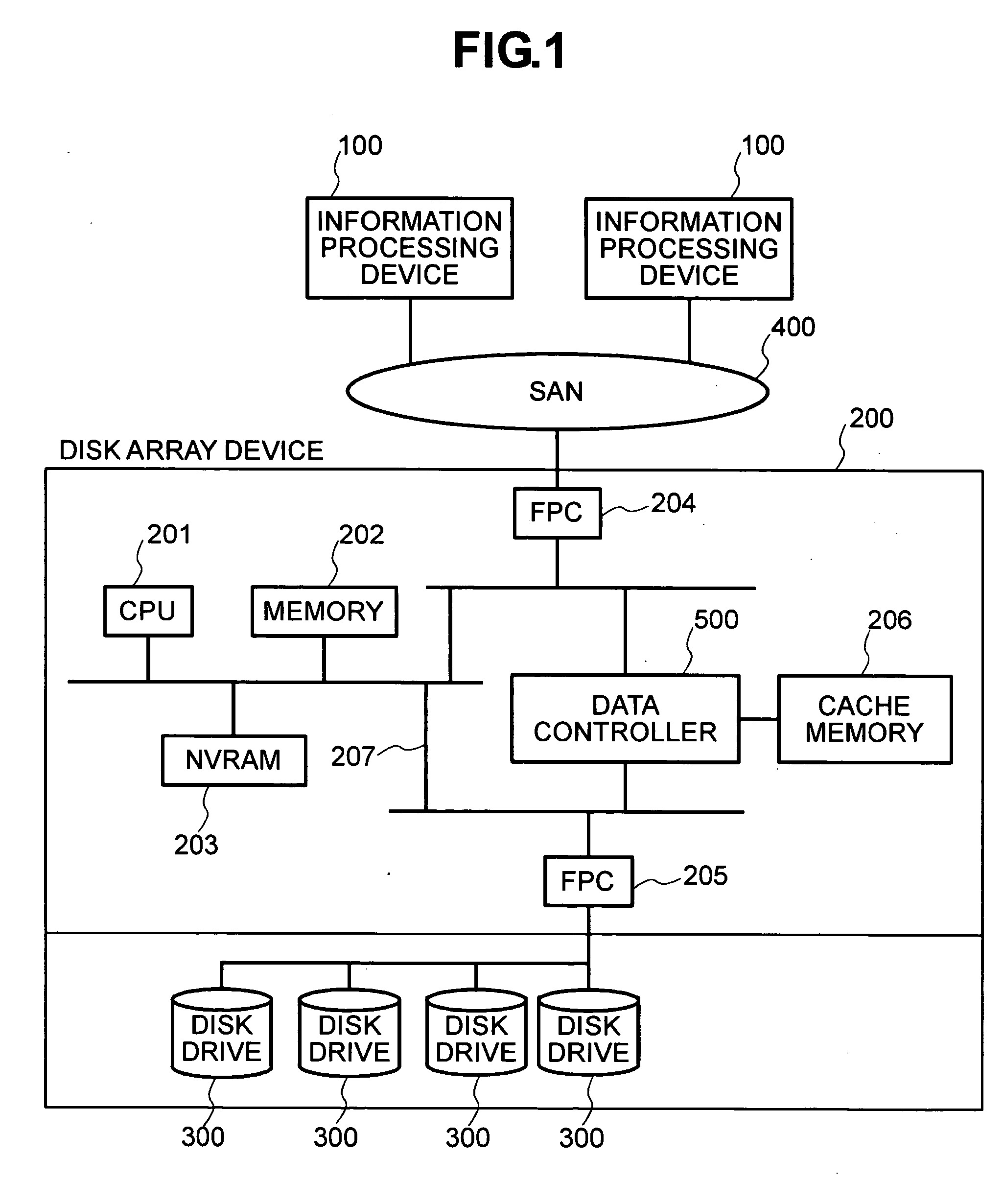
[0025]FIG. 1 is a block diagram showing the constitution of an information processing system comprising a disk array device that has the data transfer circuit of this embodiment. The ‘data transfer circuit’ is a data controller, which will be described later. The information processing system shown in FIG. 1 is constituted of an information processing device 100, which supplies a variety of information processing services, and a disk array device 200, that provides the information processing device 100 with a storage area in the form of the disk drive 300.

[0026] The information processing device 100 is a computer comprising a CPU (Central Processing Unit), memory, and so forth. The information processing device 100 implements a variety of functions as a result of various programs being run by the CPU that the information processing device 100 comprises. The information processing device 100 is a personal computer, work station, or mainframe computer, for exam...

second embodiment

[0081] Second Embodiment

[0082] Next, a description will be provided for a disk array device that represents one other embodiment of the present invention. FIG. 9 is a block diagram showing the constitution of the information processing system according to this second embodiment.

[0083] The information processing system shown in FIG. 9 has a constitution like that of the information processing system of the first embodiment. The disk array device 200 supplies the storage area of the disk drive 300 to the information processing device 100, and the information processing device 100 suitably transmits a block access request to the disk array device 200 and accesses the storage area of the disk drive 300. In this embodiment, the disk drive 300 is connected to the disk array device 200 as a storage device 310. The storage device 310 and the disk array device 200 may be connected via a communication channel in accordance with the SCSI protocol or Fibre Channel protocol. The storage device ...


PUM


Abstract

A data transfer device has a data receiver, a data control unit, and a data storage unit. In a control method for the data transfer device, the data control unit reads serial data from the storage device in block units and stores this serial data in the data storage unit. When a block constituting the write destination of the write data and a block stored in the data storage unit differ, the data control unit generates a security code, based on the serial data stored in the data storage unit, and adds the generated security code to the serial data before transferring this serial data to the storage device. The data control unit reads the serial data in the block constituting the write destination of the write data, before storing this serial data in the data storage unit, and updates the stored serial data by means of the write data.

Description

CROSS-REFERENCES TO RELATED APPLICATIONS [0001] This application relates to and claims priority from Japanese Patent Application No. 2003-314010, filed on Sep. 5, 2003, the entire disclosure of which is incorporated herein by reference. BACKGROUND OF THE INVENTION [0002] The present invention relates to a control method for controlling a data transfer device, a data transfer circuit, and a disk array device. [0003] The content of data handled by the information processing systems of recent years has become more and more important, which has in turn established a need for the reliability of storage devices. In a known method for increasing the reliability of storage devices, a security code, such as an LRC (Longitudinal Redundancy Check) code, is added to data that is stored in a storage device, such as a hard disk. Data handling between a storage device and an information processing device is performed in block units, and the security code is also added in block units. [0004] Theref...

Claims


Application Information

Patent Timeline
IPC IPC(8): G06F3/06G06F13/10G06F11/10G06F12/14
CPCG06F11/10
Inventor YAGI, SATOSHI
Owner GOOGLE LLC
Why Eureka
Try Eureka