Adaptive mapping

Inactive Publication Date: 2005-03-10
SEAGATE TECH LLC
View PDF19 Cites 17 Cited by
  • Summary
  • Abstract
  • Description
  • Claims
  • Application Information

AI Technical Summary

Benefits of technology

[0007] Embodiments of the present invention overcome the disadvantages and limitations of previous solutions by providing a system and method for providing a directory for a data storage container having one or more non-fully populated lists for sparsely filled directories. As the directory becomes more populated...

Problems solved by technology

Further, when the sparsely filled directory structures become, for example, less efficient than con...

Method used


Image

  • Adaptive mapping
  • Adaptive mapping
  • Adaptive mapping

Examples


embodiment 100

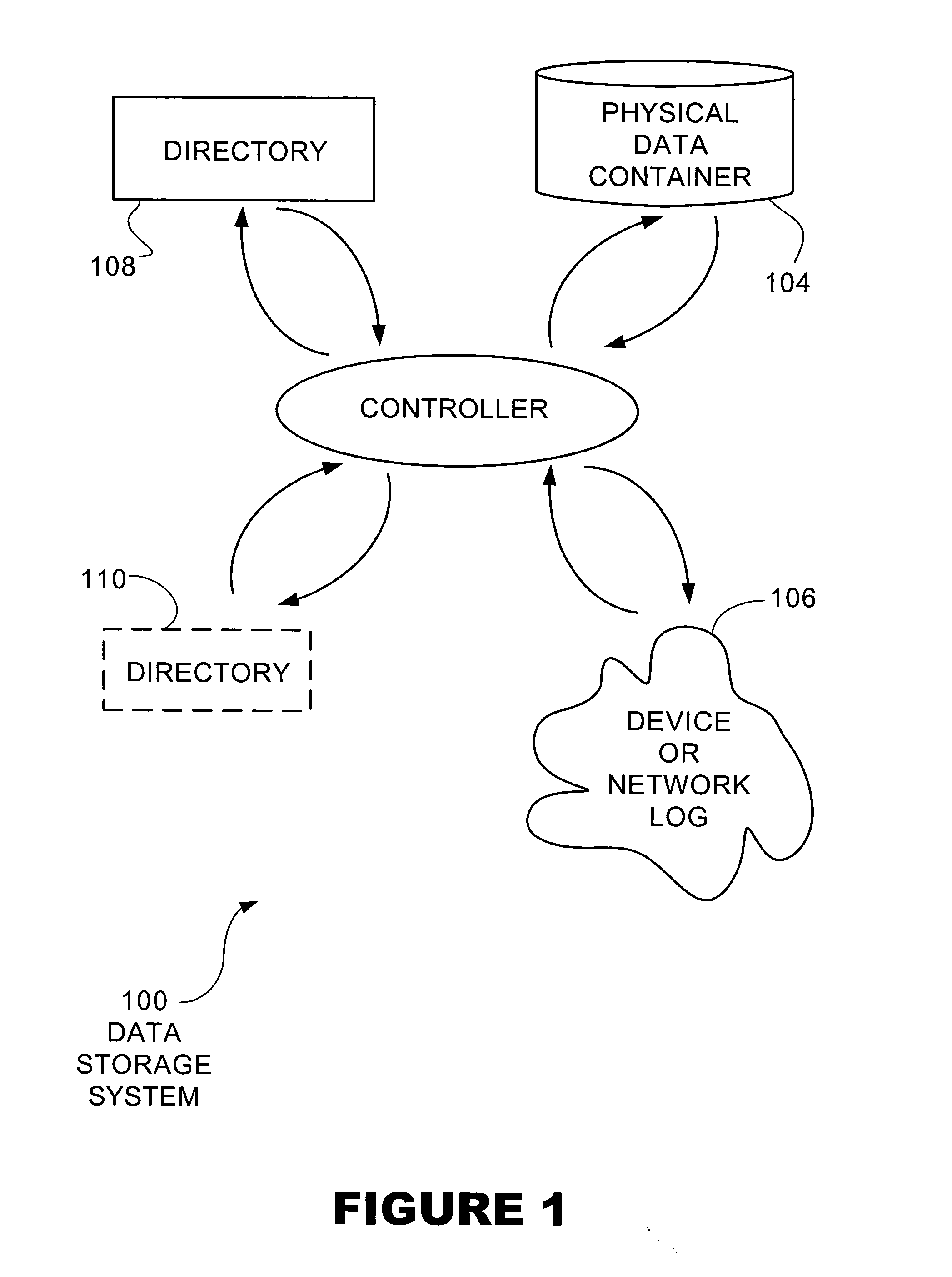
[0017]FIG. 1 illustrates an embodiment 100 of the present invention of a data storage system. A controller 102 is connected to a physical data container 104 and is operative to pass data to and from a device or network 106. The controller may use one or more directories 108 and 110 to determine the location of information in the data container 104.

[0018] The data container 104 may be any type of read / write or read only data storage medium. For example, the data container 104 may be a single disk drive or an array of disk drives such as a RAID array. While the typical application may be a disk array, the data container 104 may also be other data storage mechanisms such as flash memory or random access memory. In some cases, the data container 104 may be a virtual data container.

[0019] The controller 102 is adapted to receive and process data storage and retrieval requests from the device 106. In some embodiments, the controller 102 may be a stand alone dedicated data storage control...

embodiment 200

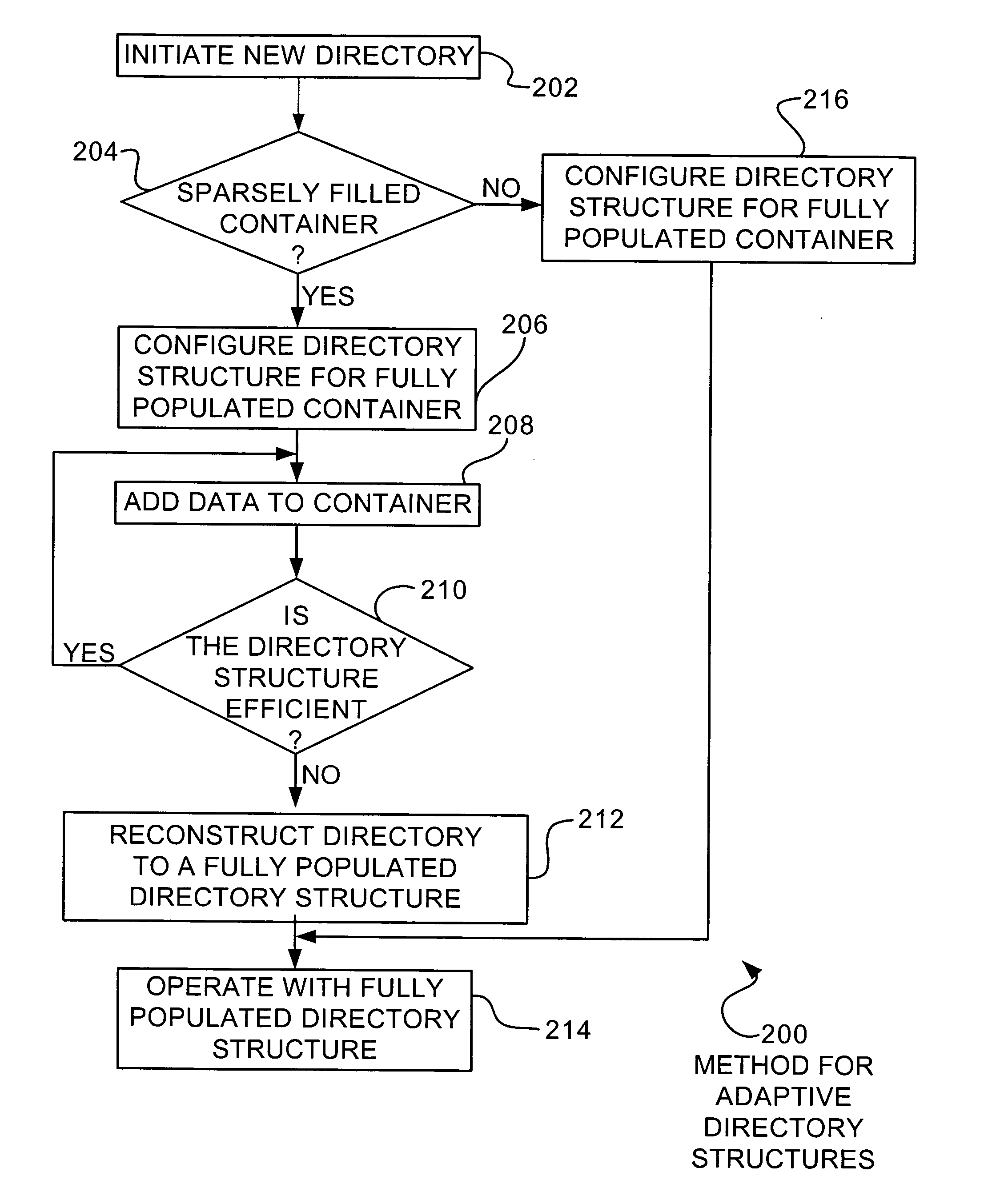
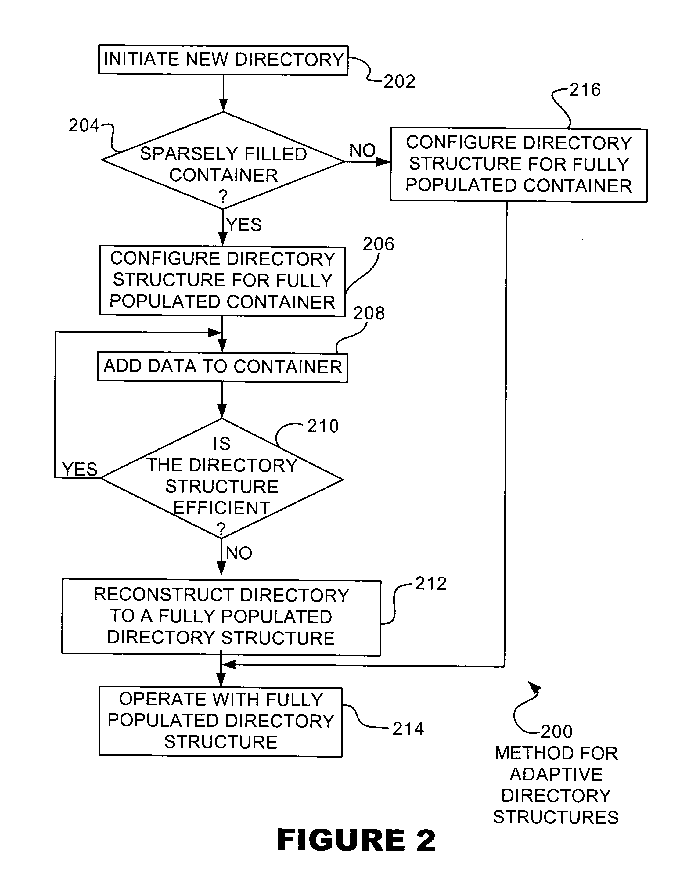
[0025]FIG. 2 illustrates an embodiment 200 of a method for adapting directory structures. A new directory is initiated in block 202. If the directory is for a sparsely filled container in block 204, the directory structure is configured for a sparsely filled container in block 206. Data is added to the container in block 208. If the directory structure is efficient in block 210, more data may be added in block 208. If the directory structure is not efficient in block 210, the directory structure is reconstructed into a structure more suited to a fully populated directory structure in block 212. The directory is operated with the fully populated directory structure in block 214. If the initial directory is not for a sparsely filled container in block 204, the directory may be configured with a fully populated directory structure in block 216 and operated in block 214.

[0026] The initiation of a new directory in block 202 may be when a new logical disk is created. The logical disk may ...

embodiment 300

[0033]FIG. 3 illustrates an embodiment 300 of the present invention of a directory structure for a sparsely filed data container. A top level map 302 may have several entries 304 that refer to the various bottom level maps 306 and 308. The bottom level map 306 may be constructed with links 312 to other entries as a linked list, doubly linked list, skip list, or other linked list data structure. Similarly, the top level map 302 may comprise links 314 and may be constructed in a form of a linked list data structure.

[0034] The directory structure 300 may include several directory entries 310. The entries 310 may include a description of the file to which it refers plus the location information for the file. Each entry 310 may also include one or more links or pointers to different entries.

[0035] The directory structure 300 may be searched by first searching the top level map 302. Each entry 304 in the top level map may indicate the approximate range of data contained in the various bo...


PUM


Abstract

A directory structure for a sparsely filled data container comprises a linked list, doubly linked list, skip list, or other non-fully populated list technique. One or more hierarchical levels of such lists may be used for sparsely filled directories. The directory structure may be converted to a conventional look-up table directory by reconstructing the directory when the directory becomes populated to certain point.

Description

FIELD OF THE INVENTION [0001] The present invention pertains to computer memory storage systems and specifically to computer memory storage systems having large virtual storage. BACKGROUND OF THE INVENTION [0002] Data storage systems can contain a directory that points to the location of information contained within the data storage system. The directory may be searched to find the location of a particular file, and then the address contained in the directory may be used to retrieve the requested file. As items are stored in the data storage system, entries are created in the directory for those items. [0003] The storage device referenced by the directory may be a single disk drive or may be an organized conglomerate of several disk drives. Various methods exist to organize several disk drives, such as the various permutations of RAID technology. In some cases, the physical storage space may be smaller than the addressable memory of the directory. Such a case may be a sparsely fille...

Claims


Application Information

Patent Timeline
IPC IPC(8): G06F12/08G06F17/30
CPCG06F17/30955G06F17/30067G06F16/902G06F16/10Y10S707/99942
Inventor LUBBERS, CLARK EDWARDROBERSON, RANDY L.
Owner SEAGATE TECH LLC
Why Eureka
Try Eureka