
Data processing apparatus, data processing method, and storage medium storing computer-readable program

Inactive Publication Date: 2005-03-10
CANON KK
View PDF24 Cites 79 Cited by
  • Summary
  • Abstract
  • Description
  • Claims
  • Application Information

AI Technical Summary

Benefits of technology

[0009] Another object of the present invention is to provide data processing apparatus and method which can cause a structure of an entire system including various devices to be visually confirmable, cause a user to easily grasp or see the entire system, and cause the entire system to be effectively used, and a storage medium which stores a computer-readable program.

Problems solved by technology

However, there is no method of functionally combining these devices with others.
For example, there is no method of combining the scanner with the printer or combining the digital copying machine with other scanner to realize a copying function.
Thus, such the method is not general.
However, when such the method nothing but displays a list of the devices, it is impossible to display, from a viewpoint of an arbitrary user as a starting point, a network system configuration in consideration of an environment in which the system structure is disposed.
This is because, by such a display, the user can not visually and easily recognize the system structure at first sight.
Further, by such the display, even when system resources used on the entire network and executing an identical function are displayed, such the resources are all displayed in undifferentiated manner.
Thus, it is impossible to discriminate the plural printers respectively having different functions only by such the displayed icons.
Further, it is impossible to correlate the system structure with its operation status and display such correlative status.
Further, since operation status of the device selected by the user is not defined, the user can not confirm such the status until input and output processing ends.
For example, since the user can not visually confirm the operation status of the selected device reflected on the network system configuration, he can not visually discriminate in the system configuration the operating device from other device or confirm by which device in the system the input and output processing is being performed.

Method used


Image

  • Data processing apparatus, data processing method, and storage medium storing computer-readable program
  • Data processing apparatus, data processing method, and storage medium storing computer-readable program
  • Data processing apparatus, data processing method, and storage medium storing computer-readable program

Examples


first embodiment

[0059]

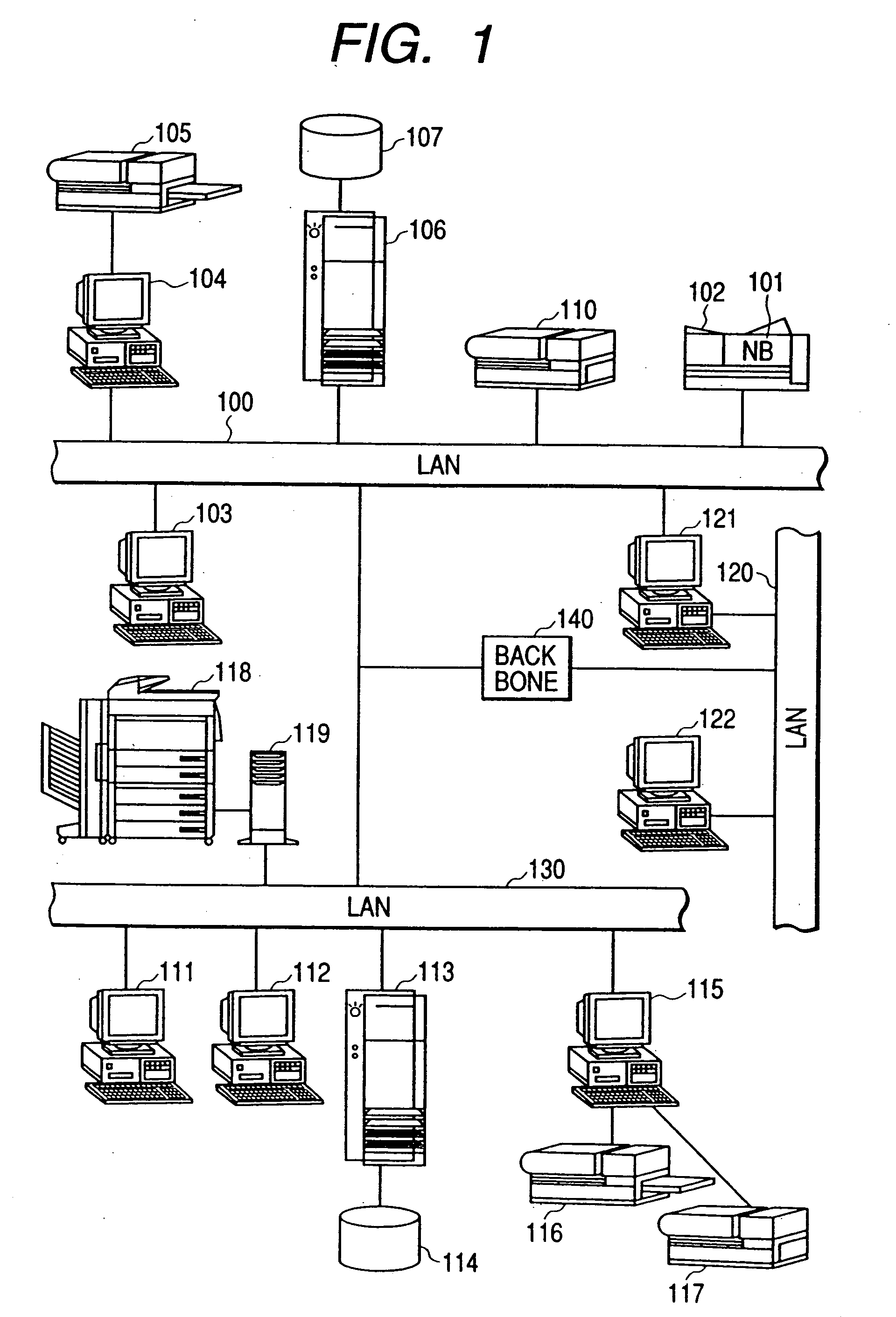
[0060]FIG. 1 is a block diagram showing a structure of a system of network devices including a data processing apparatus according to the present invention.

[0061] In FIG. 1, a printer 102 which has open-system architecture is connected with a network through an NB (network board) 101. The NB 101 is connected with LAN's 100, 120 and 130 through a local area network interface such as an Ethernet interface 10BASE2 having a coaxial connector, an Ethernet interface 10BASE-T having an RJ-45, or the like.

[0062] Plural PC's (personal computers) 103, 104, 111 and 112 are also connected with the LAN's 100 and 130, whereby these PC's can communicate with the NB 101 under the control of a network operating system.

[0063] Therefore, one of the PC's (e.g., the PC 103) can be used as the PC for network device management. Further, a printer 105 may be locally connected with the PC 104 as a local printer.

[0064] Further, since a PC 106 which functions as a file server is connected with the L...

second embodiment

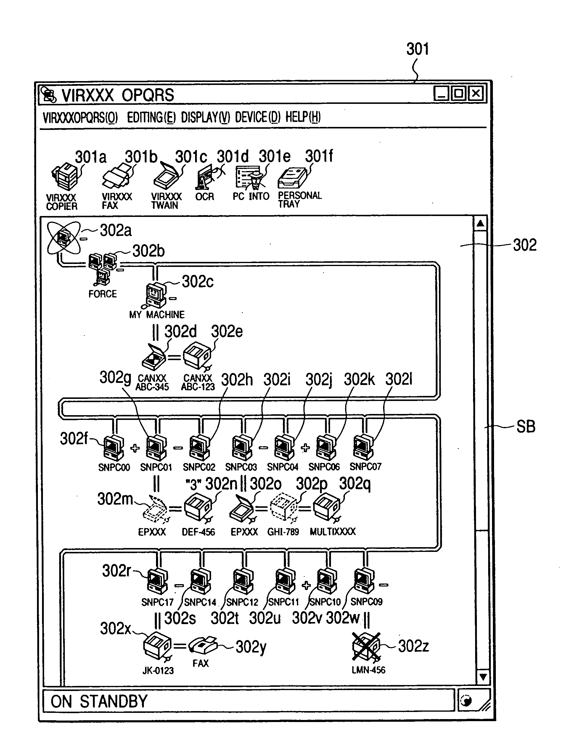
[0145] In the above-described first embodiment, it was explained the case where the device driver information is acquired from the network by communicating with the network device when each PC on the network is powered, and the device-connection information and the operation status of each device are virtual-displayed graphically by using the integrated-shaped icons which are different for the respective devices. However, the devices to be connected with the network are not limited to the printer and the scanner as described in the first embodiment. Namely, the present invention is also applicable to a case where a multifunctional device including the printer and scanner functions or a combination of these functions and other functions (including the FAX function, a database function, etc.) is connected with the network. Hereinafter, the second embodiment will be explained.

[0146]FIG. 10 is a view showing an example of the device driver information managed by the data processing app...

third embodiment

[0199] In the above-described embodiment, it was explained the case where the desired function processing is performed by the drag-and-drop operation for the virtually displayed icons of the scanner and the printer or of the scanner and the multifunctional device. However, the management server on the network can sequentially manage the information concerning a resource remaining quantity for each printer by managing such the combined function or a log for each device. Thus, log information is acquired when a log demand is issued from the PC on the network or when the function is executed, whereby it is possible to display whether or not the set function can be executed or to effectively use the log information for each device. Hereinafter, the third embodiment will be explained.

[0200]FIG. 20 is a view showing an example of the log information managed by a data processing apparatus according to the third embodiment of the present invention. In the present embodiment, either of PC's...


PUM


Abstract

The present invention allows a structure of an entire system including various peripheral devices to be visually confirmable, allows a user to easily grasp or see the entire system, and allows the entire system to be effectively used. Thus, a CPU acquires a resource information structure and a status of each peripheral device by communicating with these devices, and a virtual system configuration display unit causes a display unit to display a system configuration based on the acquired resource information structure and each peripheral device status such that specific icons capable of being discriminated for respective functions are displayed to be connected on a virtual network path.

Description

BACKGROUND OF THE INVENTION [0001] 1. Field of the Invention [0002] The present invention relates to data processing apparatus and method which can perform data communication with various devices connected on a communication medium, and a storage medium or the like which stores a computer-readable program. [0003] 2. Related Background Art [0004] In recent years, devices such as a PC (personal computer), a printer, a scanner, a digital copying machine and a digital camera have been widespread, and also a network such as a LAN (local area network) has been widespread, whereby the need to share the printer, a modem and an image reading apparatus on the network increases. Thus, by sharing apparatuses and devices on the network, an environment capable of using all of them is in order. [0005] However, there is no method of functionally combining these devices with others. For example, there is no method of combining the scanner with the printer or combining the digital copying machine wit...

Claims


Application Information

Patent Timeline
IPC IPC(8): G06F3/12B41J29/38B41J29/42G06F3/00G06F3/048G06F3/0481G06F13/00G06F15/173H04L12/24H04N1/00
CPCH04L41/22
Inventor MACHIDA, HARUO
Owner CANON KK
Features
  • Generate Ideas
  • Intellectual Property
  • Life Sciences
  • Materials
  • Tech Scout
  • Unparalleled Data Quality
  • Higher Quality Content
  • 60% Fewer Hallucinations
Learn More