Valves having a thermostatic actuator controlled by a peltier device

a thermostatic actuator and thermostatic actuator technology, applied in the field of valves, can solve the problems of high initial heat load of compressors controlled by txvs, high price of current exvs, and inability to meet the needs of customers, so as to reduce the reaction time in response to received inputs

Inactive Publication Date: 2005-03-17
MALONE STEVEN J
View PDF16 Cites 21 Cited by
  • Summary
  • Abstract
  • Description
  • Claims
  • Application Information

AI Technical Summary

Benefits of technology

[0010] The new ETXV can be configured in at least several different ways. A first configuration employs an embedded thermoelectric module utilizing both sides of the module to control a differential pressure actuator. By using both the heat-sink side and the heat-source side of the module in combination with the differential pressure actuator, reaction time in response to received inputs can be reduced. A second configuration employs only the heat-sink side of the thermoelectric module to control the valve actuator. A third configuration employs only the heat-source side of the thermoelectric module to control the valve actuator. A fourth configuration employs an external thermoelectric module having an embedded thermostatic expansion bulb connected to the valve actuator by means of a capillary tube. This configuration is preferred when heat transfer from the valve will overpower the heating or cooling effect of the thermoelectric module.

Problems solved by technology

Current EXVs are expensive, and typically utilize an electronically-controlled stepper motor that actuates the valve.
EXVs have never been used in cars because of their size and cost.
Superheat compressor loading is an important issue for large and specialized refrigeration systems, and especially those which must maintain a temperature setting below −40° Celsius / Fahrenheit.
For example, if the system needs to achieve a temperature setting of −40° Fahrenheit / Celsius, and the ambient temperature at the evaporator is 60° Fahrenheit (about 15.6° Celsius), a compressor controlled by a TXV will have a huge initial heat load.
Consequently, the compressor is subjected to a high degree of mechanical and electrical stress as it consumes large quantities of electrical energy.
As the thermal isolating heater is of the resistance wiring type, considerable is required to actuate the valve.

Method used


Image

  • Valves having a thermostatic actuator controlled by a peltier device
  • Valves having a thermostatic actuator controlled by a peltier device
  • Valves having a thermostatic actuator controlled by a peltier device

Examples


first embodiment

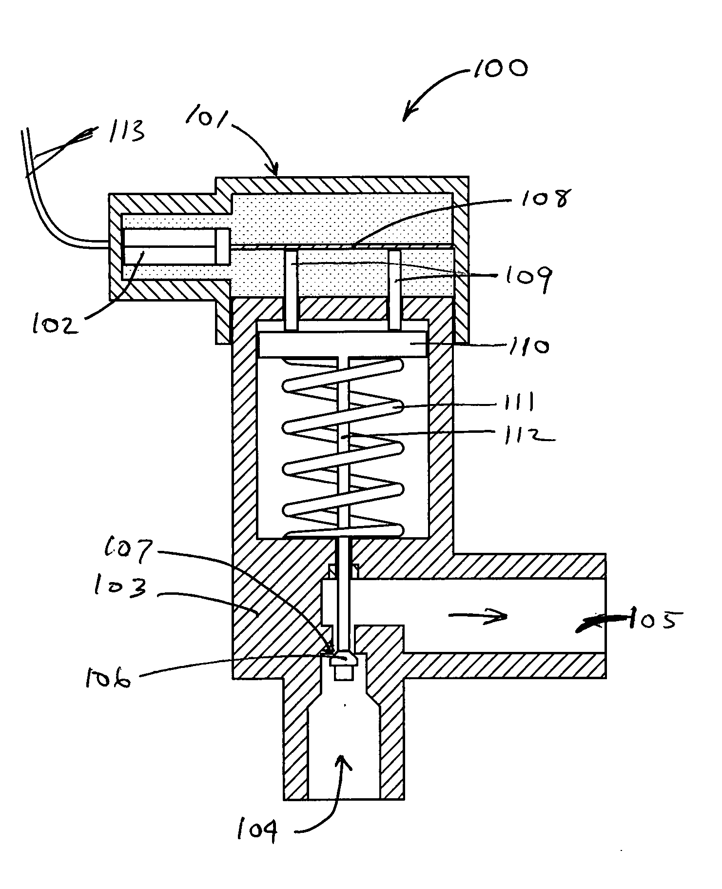
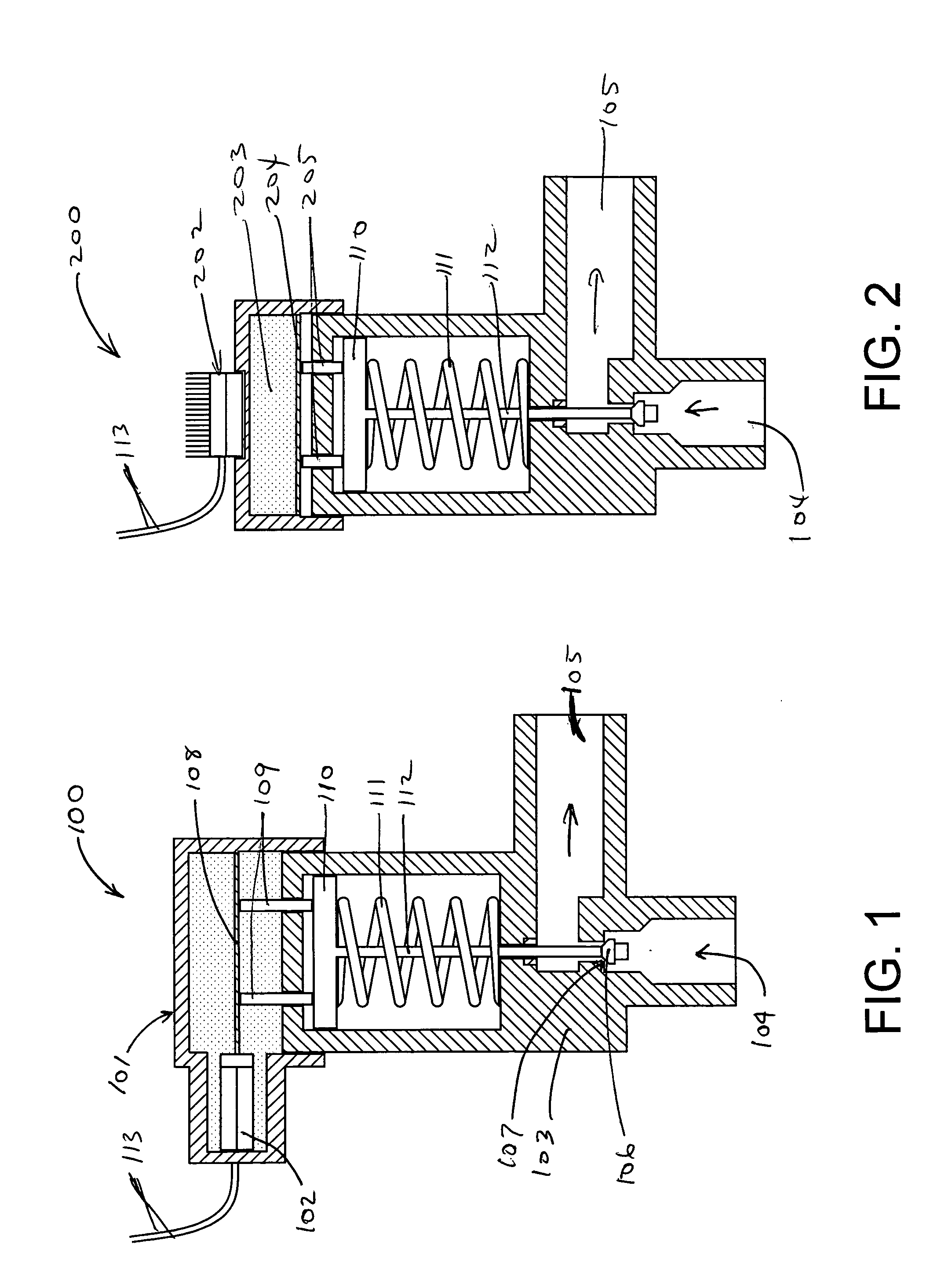
[0020] Referring now to FIG. 1, a first embodiment expansion valve 100, having a thermostatic actuator 101 controlled by both sides of a Peltier module 102, is shown. The valve 100 has a valve body 103 with an inlet 104, and an outlet 105. The passageway 106 between the inlet 104 and the outlet 105 is controlled by a conical valve plunger 106. The conical valve plunger 106 is normally pressed against the valve seat 107, but is pushed away from the seat by the expansion and contraction of gases brought about by current passing through the Peltier module 102. Gas on the top of the diaphragm 108 is exposed to the heat-source side of the Peltier module 102, while gas below the diaphragm 108 is exposed to the heat-sink side of the Peltier module 102. When current passes throught the Peltier module 102, the diaphragm 108 presses against the actuator pins 109, which in turn press on the actuator disk 110, thereby overcoming the force exerted by the coil spring 111 and depressing the vertic...

second embodiment

[0021] Referring now to FIG. 2, a second embodiment expansion valve 200 having a thermostatic actuator 201 controlled by both sides of a Peltier module 202, is shown. The lower portion of the expansion valve is identical to that of FIG. 1. However, it will be noted that there is a gas reservoir 203 only on top of the diaphragm 204. When the Peltier module 202 heats gas within the gas reservoir 203, the diaphragm 204 presses against the actuator pins 205, which in turn press on the actuator disk 110, thereby overcoming the force exerted by the coil spring 111 and depressing the vertical connector rod 112 that is directly coupled to the valve plunger 106.

third embodiment

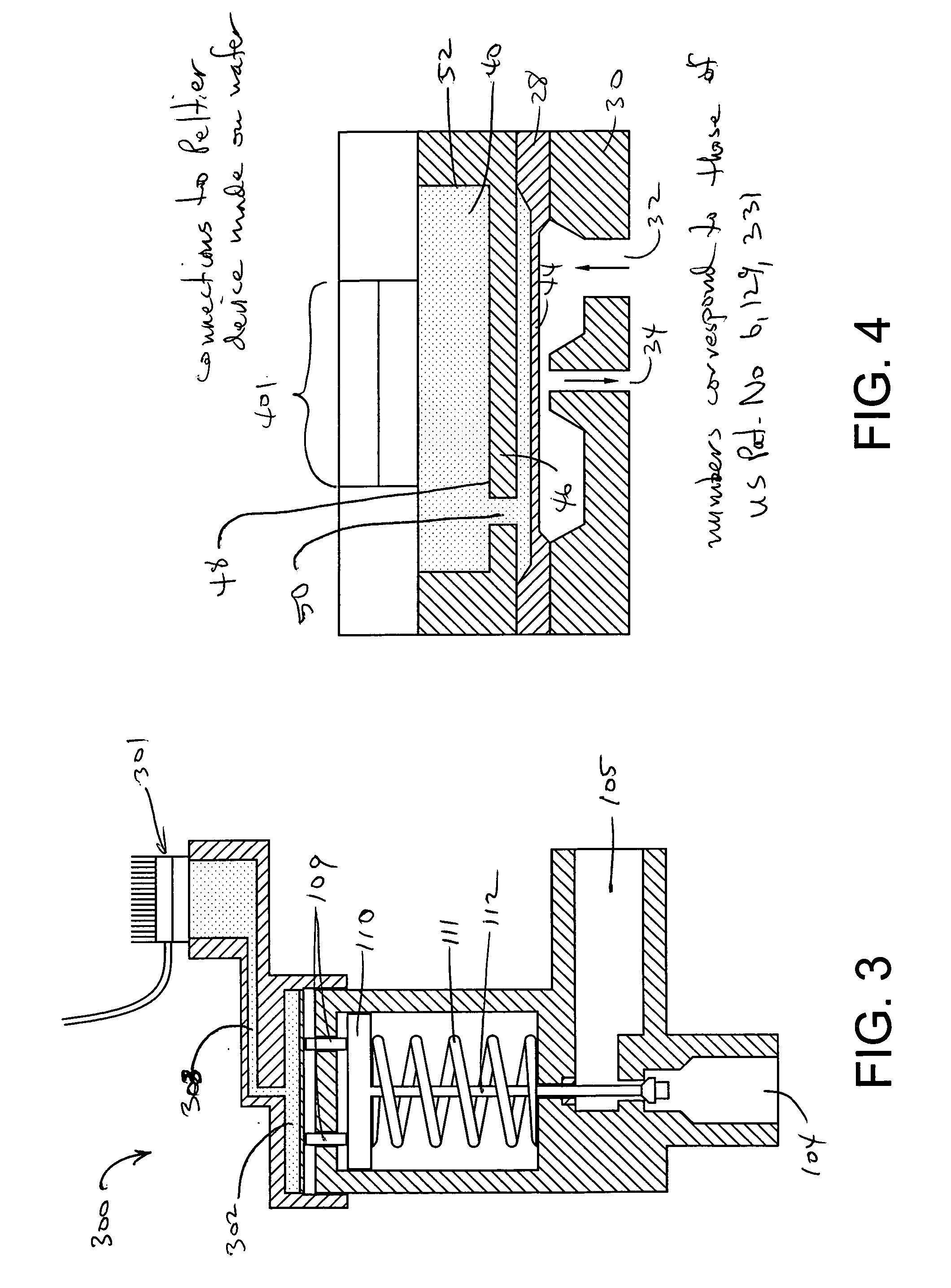
[0022] Referring now to FIG. 3, a third embodiment expansion valve 300 has an external Peltier module 301 with an embedded thermostatic expansion bulb 302 connected to the valve by means of a capillary tube 303. Such a configuration is useful when the heat loss through the valve is greater than the heat that a Peltier module directly coupled to the valve could generate. By isolating the Peltier module 301 from the valve, the valve may be operated using reduced power requirements.

[0023] Referring now to FIG. 4, the valve of U.S. Pat. No. 6,129,331 has been modified in accordance with the present invention to have a Peltier device 401 in place of a thermal isolating heater. U.S. Pat. No. 6,129,331 is hereby incorporated by reference into the present document.

[0024]FIG. 5 is a diagramatic view of a closed-loop refrigeration control system 500. The system 500 includes a mirco-controller 502 having set point inputs 501, an electronically-contolled thermal expansion valve 503 incorporati...


PUM


Abstract

An electro-thermostatic expansion valve (ETXV) includes a valve body having a thermostatic actuator controlled by a Peltier thermoelectric module. The valve may be electronically controlled in response to measured parameters at critical locations in refrigeration, heating, pneumatic and hydraulic systems. A preferred method of controlling the ETXV valve involves the use of pressure or temperature sensors located on the expansion head of the ETXV or on an external device controlled by the ETXV. The sensors provide feedback signals to a micro-controller, and the micro-controller directly controls the thermoelectric module. An alternate method of controlling the new ETXV involves the use of operator inputs provided to a micro-controller which controls the thermoelectric module. The operator can manually adjust the micro-controller in response to observed process parameters. The ETXV can be configured to use one or both sides of the thermoelectric module to control the valve actuator.

Description

[0001] This application has a priority date based on Provisional Patent Application No. 60 / 502,057, which was filed on Sep. 11, 2003.BACKGROUND OF THE INVENTION [0002] 1. Field of the Invention [0003] This invention relates generally to valves for controlling the flow of fluids and gasses. More particularly, this invention relates to a low-power electronically controlled valve that is particularly useful for proportional flow control of liquids such as those used in refrigerant applications. [0004] 2. Description of the Prior Art [0005] Inexpensive electronic control of refrigerant expansion does not presently exist. Most contemporary refrigeration systems use a mechanically-controlled thermal expansion valve (TXV). Electronic control is superior to mechanical control in many ways. User control of evaporator pressure / temperature set points, superheat loading of the compressor, and greater general pressure / temperature stability make an electronically-controlled thermal expansion valv...

Claims


Application Information

Patent Timeline
Patent Type & Authority Applications(United States)
IPC IPC(8): G05D23/19
CPCG05D23/1921
Inventor MALONE, STEVEN J.
Owner MALONE STEVEN J
Why Eureka
Try Eureka