
Algorithm for automatic logout of objects in a database

a database and object technology, applied in the field of automatic logout of objects in databases, can solve the problems of difficult to determine to which object nodes the connector line is associated, difficult for users to make much sense of the display, and difficult for users to determine the connection of the node to the object node, so as to improve the visual understanding of the network and simplify the network view

Active Publication Date: 2005-03-17
ORACLE INT CORP
View PDF4 Cites 6 Cited by
  • Summary
  • Abstract
  • Description
  • Claims
  • Application Information

AI Technical Summary

Benefits of technology

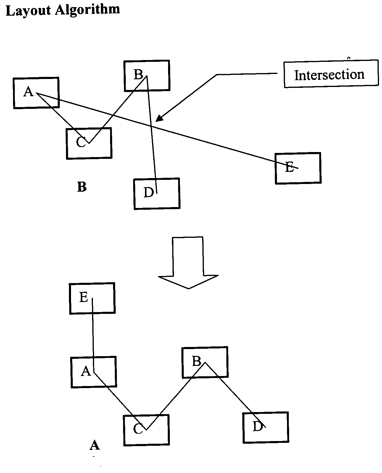
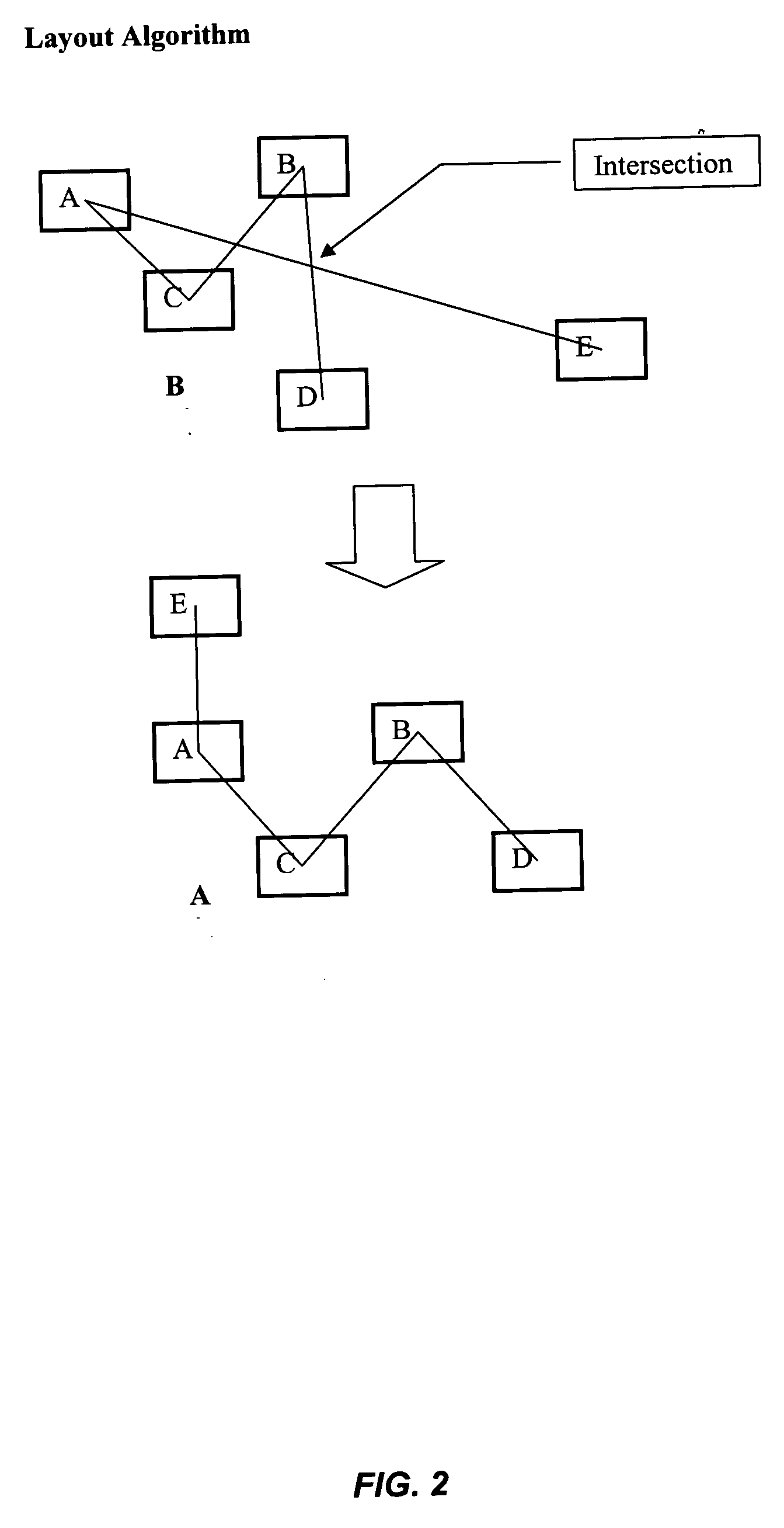
[0005] The present invention provides systems and methods for arranging, and re-arranging, interconnected network nodes in a display in a manner that simplifies the network view, and therefore also improves the visual understanding of the network imparted to a viewer of the display.
[0010] According to yet another aspect of the present invention, a computer system configured to automatically re-arrange nodes in a display is provided. The system typically includes a display for displaying node configurations, wherein a plurality of nodes is displayed in a first configuration on the display, wherein each node has associations with one or more nodes, and wherein each association is represented by a physical connector between the associated nodes on the display. The system also typically includes a means for automatically re-arranging the displayed nodes to a second configuration on the display such that a total length of all connectors is minimized and such that a number of overlapping connectors is minimized.

Problems solved by technology

However, such network topology displays become very confusing for large topologies (e.g., large number of objects and associations): the user is often presented with a complex web of tangled connections.
Above a certain level of network complexity, it becomes difficult for the user to make much sense of the display and to determine which nodes are connected.
Consequently, it may be very difficult to determine to which object nodes the connector line is associated.
Current development tools, such as Rational Rose and Oracle's JDeveloper, only provide limited means for re-organizing object nodes and do not provide a robust automatic solution to such problem.

Method used


Image

  • Algorithm for automatic logout of objects in a database
  • Algorithm for automatic logout of objects in a database
  • Algorithm for automatic logout of objects in a database

Examples


Embodiment Construction

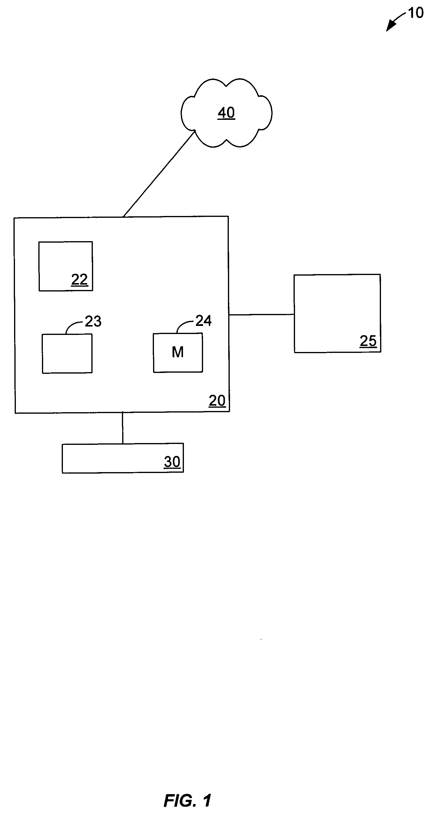
[0017]FIG. 1 illustrates an exemplary display system 10 according to the present invention. Display system 10 includes a client device 20, coupled to, or including a display device 25 and a user interface device 30. Client device 20 could be a desktop personal computer, workstation, laptop computer, or any other computing device. Client device 20 preferably includes components capable of interfacing directly or indirectly with a network 40. Network 40 can be the Internet, a local area network (LAN), wide area network (WAN), virtual private network (VPN) or any other type of network. Each client 20 typically runs an application program 22 allowing a user of client 20 to create and visualize a topology of network nodes as will be discussed in more detail below. Each client device 20 also typically includes one or more user interface devices 30, such as a keyboard, a mouse, touchscreen, pen or the like, for interacting with a graphical user interface (GUI) provided by the application p...


PUM


Abstract

Systems and methods that automatically arrange, or re-arrange, object nodes in a diagram such that the total length of all associations between nodes and the number of overlapping associations is reduced or minimized. In mathematical terms, the process simplifies the graphical representation of an arbitrary graph. In one aspect, processes of the invention use a physical model of particle interactions to determine a minimal energy state, with object nodes modeled as particles and the associations between the object nodes modeled as interaction forces. Perturbations applied to the system allow for a determination of a minimal energy state

Description

BACKGROUND OF THE INVENTION [0001] The present invention relates to systems and methods for simplifying nodes in a network display, and more particularly to systems and methods for simplifying an object model display by automatically arranging or re-arranging objects in the model. [0002] One goal of modeling systems, such as the Unified Modeling Language (UML) and other modeling systems, is to provide a means to specify, construct, document and visualize the artifacts of a distributed system such as a distributed object system in the case of UML. The display rendered in such systems provides the user with a visual feedback that allows the user to simply and easily understand the model paradigm being created or implemented. In the case of UML, or other object modeling systems, object nodes are displayed in a topology along with relationships (e.g., associations) between the various object nodes so as to create an object network topology. Object nodes are typically connected by connec...

Claims


Application Information

Patent Timeline
IPC IPC(8): H04L12/24
CPCH04L41/22H04L41/12
Inventor NICKOLAYEV, OLEGTHOMPSON, DAVIDKUNTAWAR, YOGESHWAR WAMANRAOBROGOCH, LAURA ANNE
Owner ORACLE INT CORP
Learn More