Color picture tube apparatus

a tube apparatus and tube tube technology, applied in the field of color picture tube apparatus, can solve the problems of increasing cost, inability to obtain sufficient sensitivity, and new ringing, and achieve the effect of improving image quality

Inactive Publication Date: 2005-03-17
MATSUSHITA TOSHIBA PICTURE DISPLAY CO LTD
View PDF3 Cites 6 Cited by
  • Summary
  • Abstract
  • Description
  • Claims
  • Application Information

AI Technical Summary

Benefits of technology

[0015] The present invention solves the above-mentioned conventional problems, and its object is to provide a color picture tube apparatus with image quality enhanced, in which a ring-shaped ferrite core for intensifying the magnetic field of BVM coils, attached together with magnet rings of a CPU, is unlikely to be cracked.

Problems solved by technology

However, the above-mentioned method has the following problems: since a magnetic substance for focusing a magnetic field is metal, a new eddy current is likely to be generated; a process for welding a new component is necessary, which increases a cost; and furthermore, sufficient sensitivity cannot be obtained.
However, in this case, the BVM coils are placed close to a horizontal deflection coil, so that crosstalk between the magnetic field generated by the BVM coils and the horizontal deflection magnetic field is increased to cause new ringing.
Therefore, there is a limit for placing the BVM coils close to the deflection yoke, and hence, a sufficient increase in sensitivity cannot be realized.

Method used


Image

  • Color picture tube apparatus
  • Color picture tube apparatus
  • Color picture tube apparatus

Examples


embodiment 1

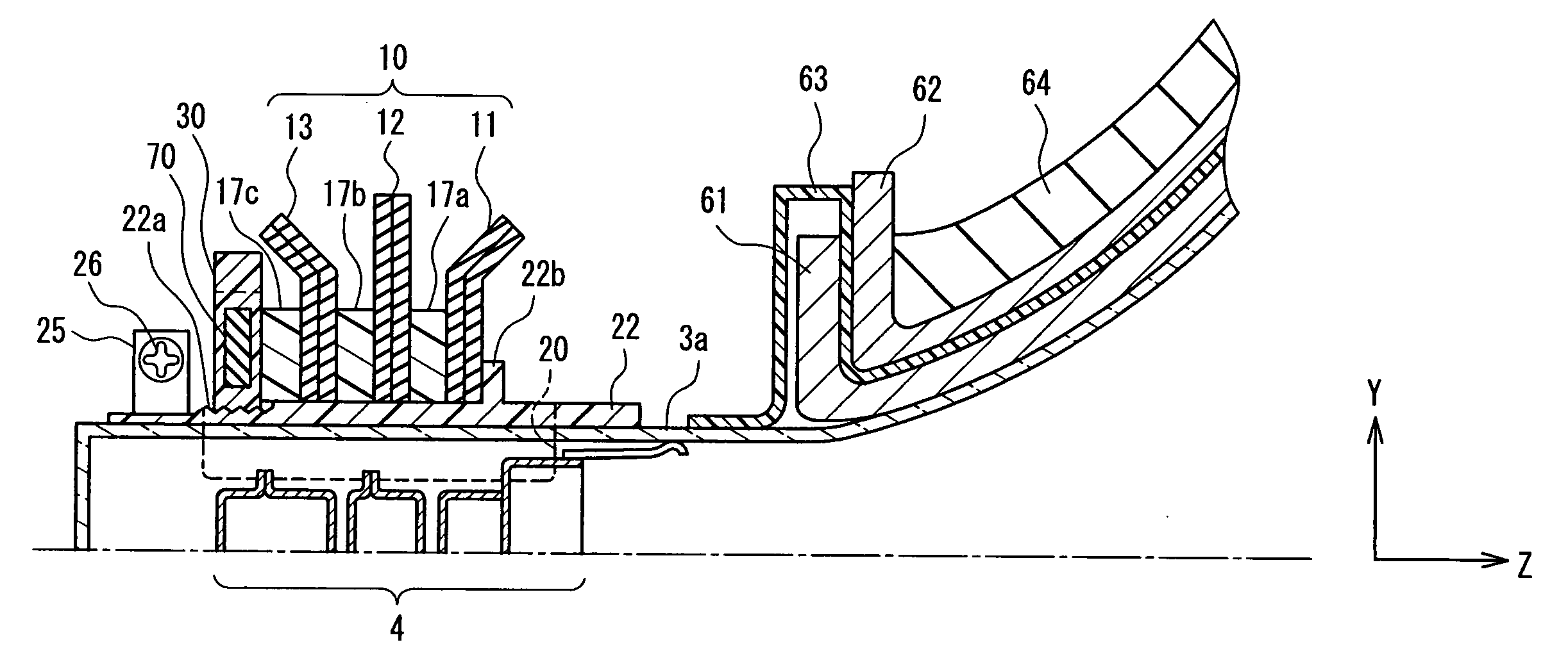
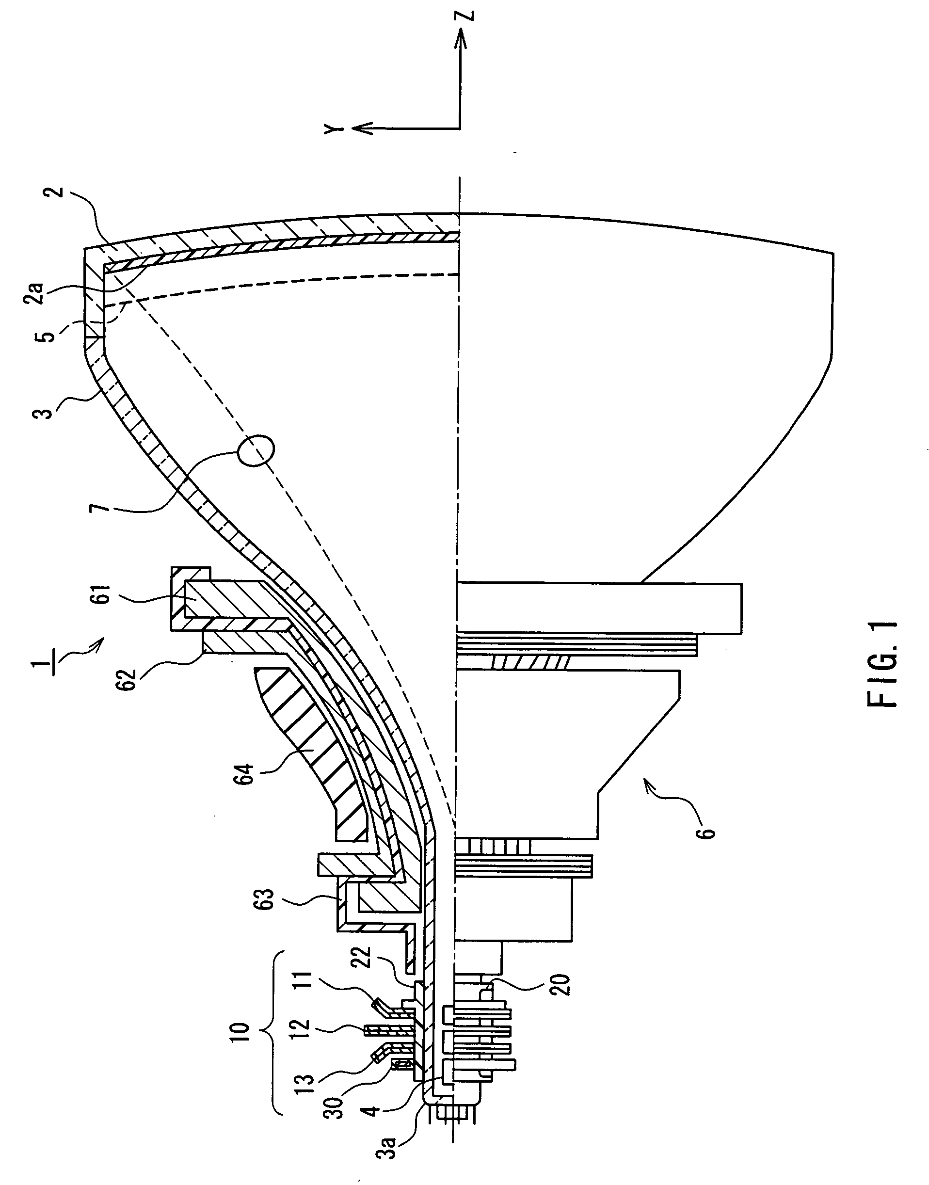
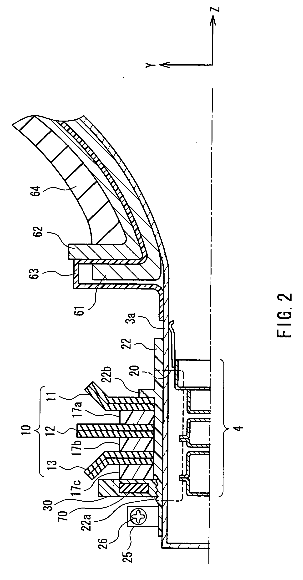
[0030]FIG. 1 is a view showing a configuration of a color picture tube apparatus according to Embodiment 1 of the present invention. For convenience of the following description, it is assumed that a tube axis is a Z-axis, an axis in a horizontal direction (long side direction of a screen) is an X-axis, and an axis in a vertical direction (short side direction of a screen) is a Y-axis. The X-axis and the Y-axis cross each other on the Z-axis. In FIG. 1, a cross-sectional view and an outer appearance view are shown on an upper side and a lower side of the Z-axis, respectively.

[0031] A color picture tube (CRT) includes an envelope composed of a panel 2 and a funnel 3, and an electron gun 4 provided in a neck portion 3a of the funnel 3. A color picture tube apparatus 1 includes the color picture tube and a deflection yoke 6 mounted on an outer circumferential surface of the funnel 3. On an inner surface of the panel 2, a phosphor screen 2a is formed, in which respective phosphor dots ...

embodiment 2

[0043] In Embodiment 1, the example has been described, where the present invention is applied to a color picture tube apparatus with a CPU mounted thereon, in which the dipole, quadrupole, and hexapole magnet rings 11, 12, and 13 are fixed with the screw thread tightening force of the lock ring. In Embodiment 2, an example will be described, where the present invention is applied to a color picture tube apparatus with a CPU mounted thereon, in which the dipole, quadrupole, and hexapole magnet rings 11, 12, and 13 are fixed with the elastic force of an elastic ring.

[0044] The color picture tube apparatus of Embodiment 2 is the same as the color picture tube apparatus 1 of Embodiment 1 shown in FIG. 1, except for the circumferential configuration of the CPU 10. In the following description, the same components as those in Embodiment 1 are denoted with the same reference numerals as those therein, and the detailed description thereof will be omitted here.

[0045]FIG. 5 is a partial cr...

embodiment 3

[0058] In Embodiments 1 and 2, the example has been described in which, due to the resin molding integral with the ring core 70, the two surfaces orthogonal to the Z-axis of the ring core 70 are covered with resin layers. However, the present invention is not limited thereto. For example, the two surfaces orthogonal to the Z-axis of the ring core 70 may be covered with resin layers by placing the ring core 70 in a housing previously obtained by resin molding.

[0059]FIG. 8A is an exploded perspective view of a spacer ring 17′ according to Embodiment 3, and FIG. 8B is a side view thereof. The spacer ring 17′ is composed of a ring core 70 and a housing 80 accommodating the ring core 70. The housing 80 is composed of a first member 81 and a second member 82 that are molded of resin. The ring core 70 is placed in a space formed by combining the first member 81 with the second member 82. At least one of the spacer rings 17a, 17b, and 17c shown in Embodiments 1 and 2 can be replaced with t...


PUM


Abstract

A CPU for adjusting color purity and color displacement at the center of a screen is provided on an outer circumferential surface of a neck portion. BVM coils for modulating a scanning velocity in a horizontal direction of electron beams are provided at a position where they are overlapped with the CPU in a tube-axis direction. A ring-shaped ferrite core is provided at a position where it is overlapped with the BVM coils in the tube axis direction. Two surfaces vertical to a tube axis of the ring-shaped ferrite core are covered with resin layers. Because of this, the ring-shaped ferrite core can be prevented from being cracked.

Description

BACKGROUND OF THE INVENTION [0001] 1. Field of the Invention [0002] The present invention relates to a color picture tube apparatus. [0003] 2. Description of the Related Art [0004] In order to correct an edge of a displayed image to enhance image quality, a method for modulating a horizontal scanning velocity of electron beams is known. According to this method, in general, a pair of auxiliary coils called beam velocity modulation (BVM) coils are provided at a neck portion of a picture tube so as to be integrated with a deflection yoke and a convergence and purity unit (CPU) (see JP57(1982)-45650Y). [0005] The BVM coils improve a visible state between a dark area and a light area of an image displayed on a screen during a horizontal scanning period as follows. The transition of a lighting state is predicted from a video signal waveform. In a period on a dark side during a transition period of a lighting state, electron beams are accelerated so that they are horizontally scanned at a...

Claims


Application Information

Patent Timeline
Patent Type & Authority Applications(United States)
IPC IPC(8): H01J29/76
CPCH01J29/76
Inventor IWASAKI, KATSUYO
Owner MATSUSHITA TOSHIBA PICTURE DISPLAY CO LTD
Why Eureka
Try Eureka