

Projection display
- Summary
- Abstract
- Description
- Claims
- Application Information
AI Technical Summary
Benefits of technology
Problems solved by technology
Method used
Image

Examples
Embodiment Construction
[0034] Reference will now be made in detail to the embodiments of the present invention, examples of which are illustrated in the accompanying drawings, wherein like reference numerals refer to the like elements throughout. The embodiments are described below in order to explain the present invention by referring to the figures.
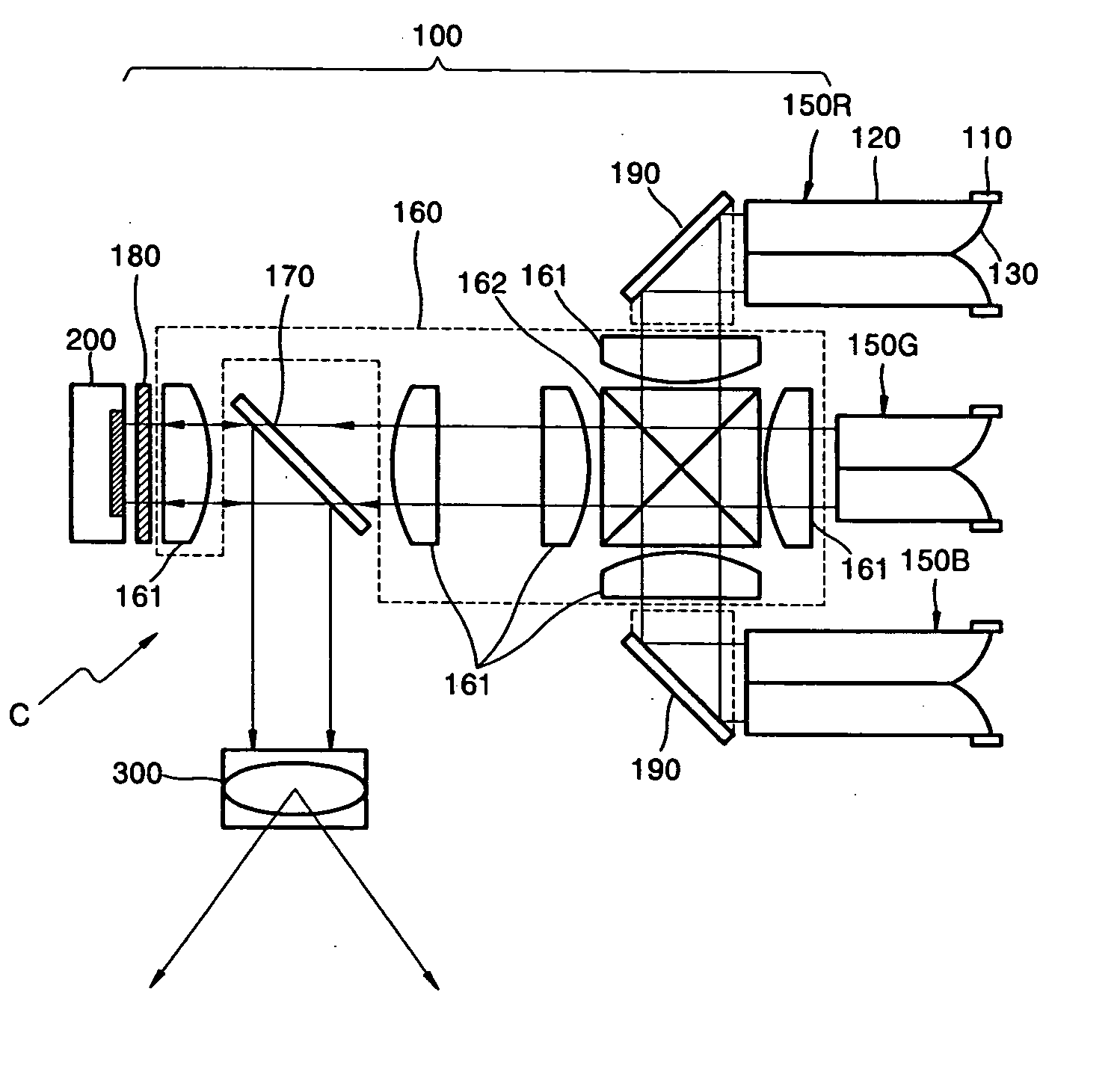
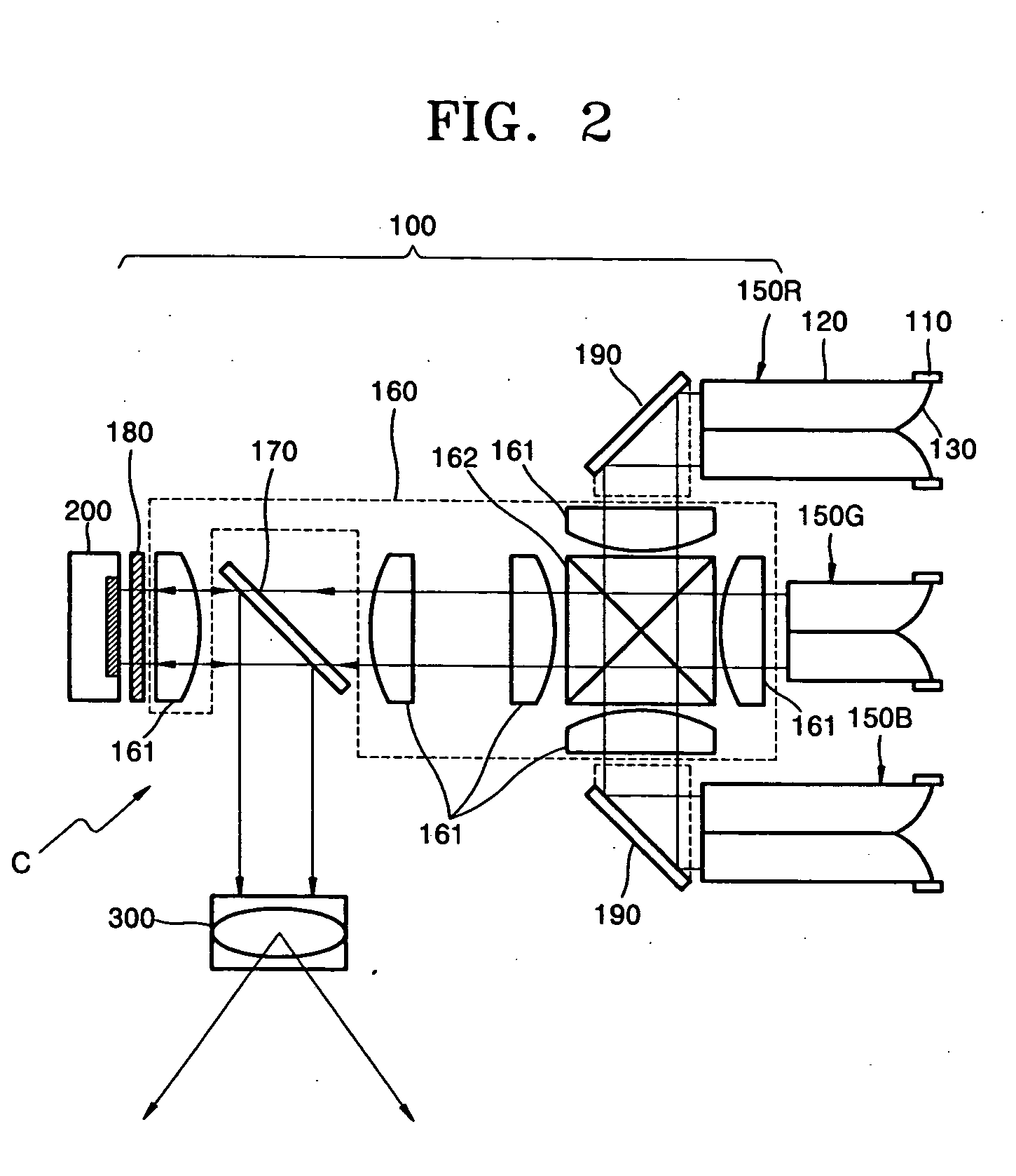
[0035]FIG. 2 is a view showing a structure of a projection display according to an embodiment of the present invention. Referring to FIG. 2, the projection display includes an illumination unit 100, an optical modulator 200, and projection optics 300. The optical modulator 200 modulates a light beam radiating from the illumination unit 100 to be suitable for image data, and then emits the modulated light beam. In the present embodiment, the optical modulator 200 is a reflective optical modulator. The reflective optical modulator may be a digital mirror device (DMD), an LCD panel, a liquid crystal on silicon (LCOS) panel, or the like. In this embodiment, the ...
PUM
 Abstract
Description
Claims
Application Information