Methods and apparatus for offset chirp modulation

a chirp modulation and offset technology, applied in the direction of pulse combined modulation, multiplex communication, orthogonal multiplex, etc., can solve the problems of difficult to achieve reliable information transmission, such as an acceptable bit error rate in the context of digital signals, fading and interference may occur within a channel, etc., to solve the range ambiguity and spread the signal over a larger bandwidth

Active Publication Date: 2005-03-17
VEONEER US LLC
View PDF2 Cites 16 Cited by
  • Summary
  • Abstract
  • Description
  • Claims
  • Application Information

AI Technical Summary

Benefits of technology

This patent describes methods and devices for creating special types of signals called chirp signals that can help resolve issues like range uncertainty and interference when sending information through wireless networks. These chirp signals contain specific patterns of variation in frequency over time that make them useful for various applications including position tracking and data transfer. The method involves combining two separate inputs with different timing delays and coding symbols, resulting in a complex waveform that contains all the necessary components needed for successful communication. The device includes both a transmitter for generating the chirp signals and a receiver for extracting the desired information from the received signals. Overall, this technology provides improved performance and reliability for wireless communications systems.

Problems solved by technology

The patent text discusses the challenges of transmitting information through modulated waveforms, such as radar and cellular telephones, due to fading and interference. The text also highlights the need for methods and apparatus that can minimize these problems and provide a more efficient way to transmit information. Additionally, the text mentions the advantage of covert transmission and the need for a transmitted waveform that is both difficult to detect and decode/demodulate in certain military applications.

Method used


Image

  • Methods and apparatus for offset chirp modulation
  • Methods and apparatus for offset chirp modulation
  • Methods and apparatus for offset chirp modulation

Examples


Embodiment Construction

[0021] The present invention comprises methods and systems for providing modulation schemes, and in particular modulation schemes that include what is referred to herein as offset chirp modulation (OCM).

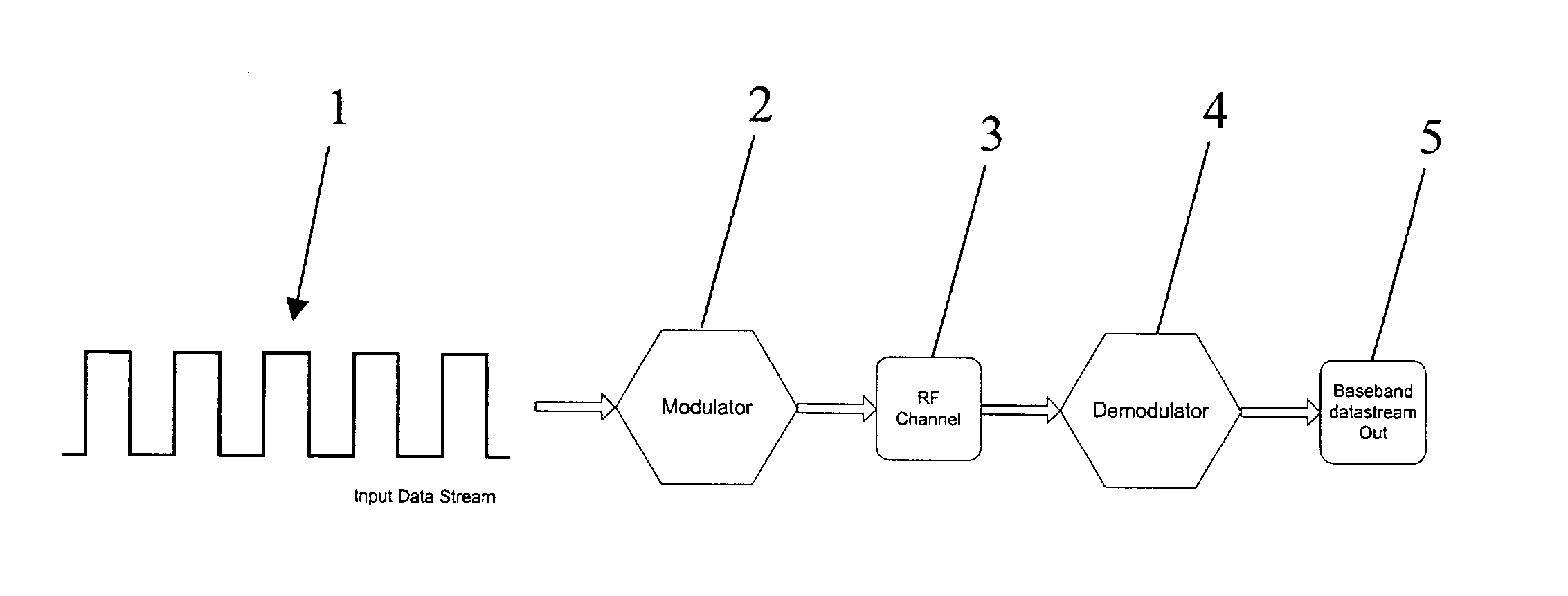
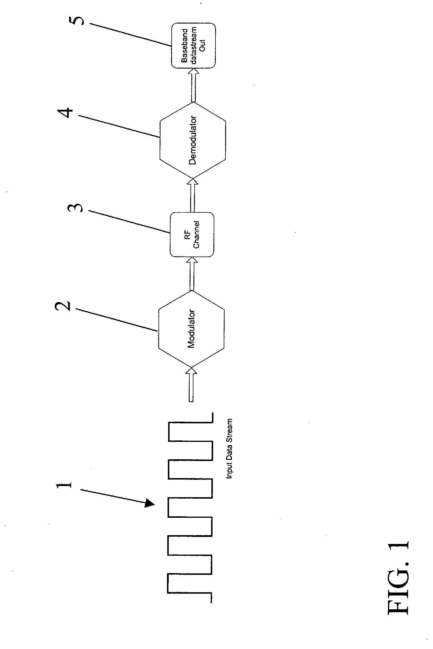
[0022] For the modulation scheme in accordance with one embodiment of the present invention, an input data stream, a modulator, a physical channel or transmission medium, and a demodulator are used. FIG. 1 presents a representative block diagram of various features for one example of a modulation scheme, in accordance with an embodiment of the present invention. These features include an input data stream 1, which is passed in turn to a modulator 2, which produces a transmission 3, such as a radio frequency (RF) transmission in a particular channel, a demodulator 4, and a baseband datatstream output 5, such as data corresponding to received wave information.

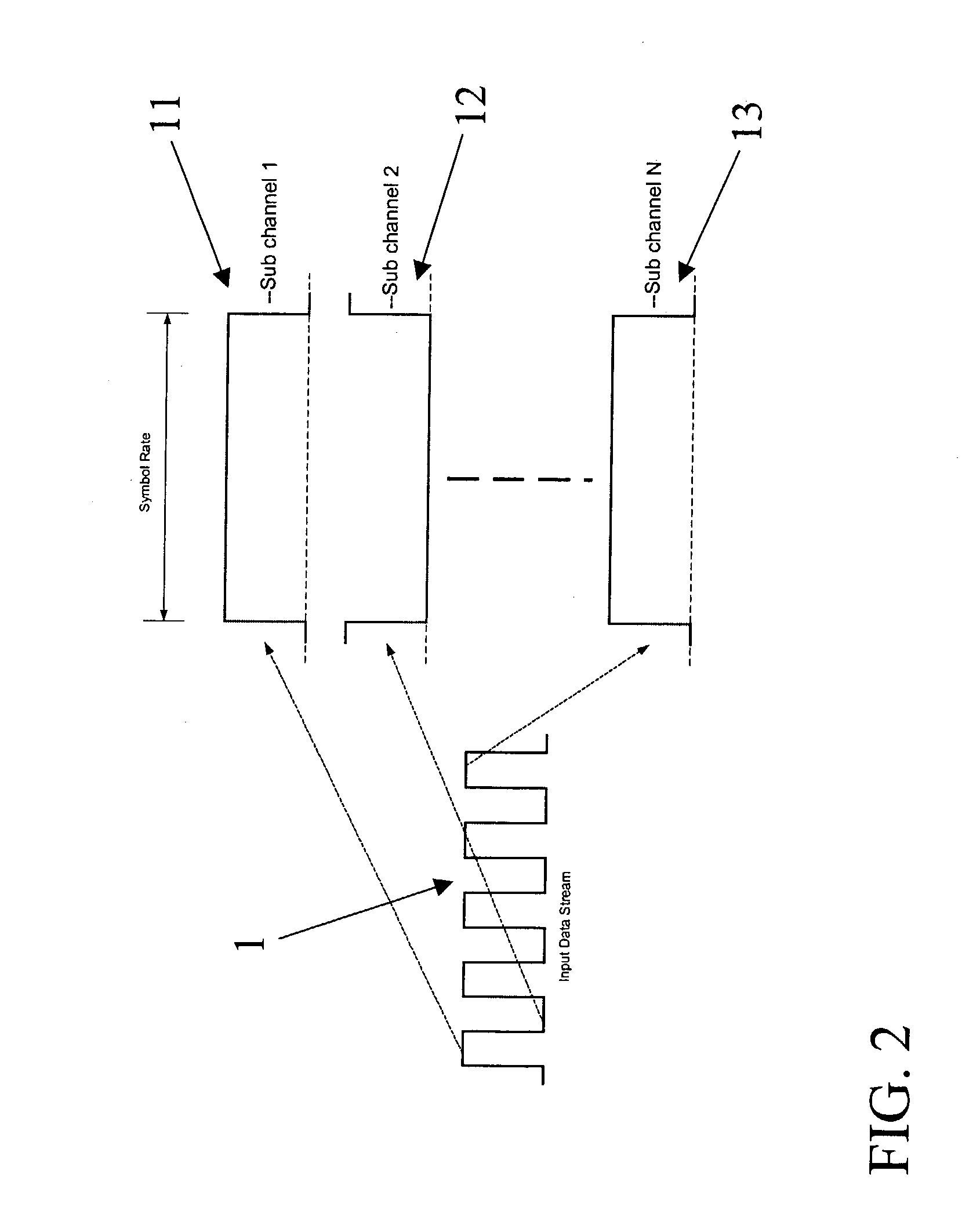
[0023] In one embodiment of the present invention, in operation, first a high data rate input stream (e.g., IP bits / s) is mult...


PUM


Abstract

A method and apparatus for producing a modulation scheme usable in conjunction with information transmission and reception via waveforms, such as electromagnetic waves. The modulation scheme is usable for such purposes as resolving range ambiguities and overcoming fading and interference problems via use of offset signals that vary in frequency over time (e.g., chirp signals), which spread the signal over a larger bandwidth. The method includes coding a symbol signal onto a split data stream containing a reference signal (e.g., a chirp), to which a time delay has been applied, then recombining the split streams to produce a composite waveform. The method can also include demodulating a composite received waveform by applying a reference signal to the waveform and then band pass filtering the waveform into discrete symbol data. Apparatus and systems are also provided for performing the method.

Description


Claims


Application Information

Patent Timeline
Owner VEONEER US LLC
Why Eureka
Try Eureka