
Non-volatile memory structure

a memory structure and non-volatile technology, applied in the field of flash memory devices, can solve the problems of high erase voltage, high tunneling barrier, high voltage, etc., and achieve the effect of reducing the number of erase/write cycles, and accelerating the erasing speed

Inactive Publication Date: 2005-03-17
ROUND ROCK RES LLC
View PDF99 Cites 7 Cited by
  • Summary
  • Abstract
  • Description
  • Claims
  • Application Information

AI Technical Summary

Benefits of technology

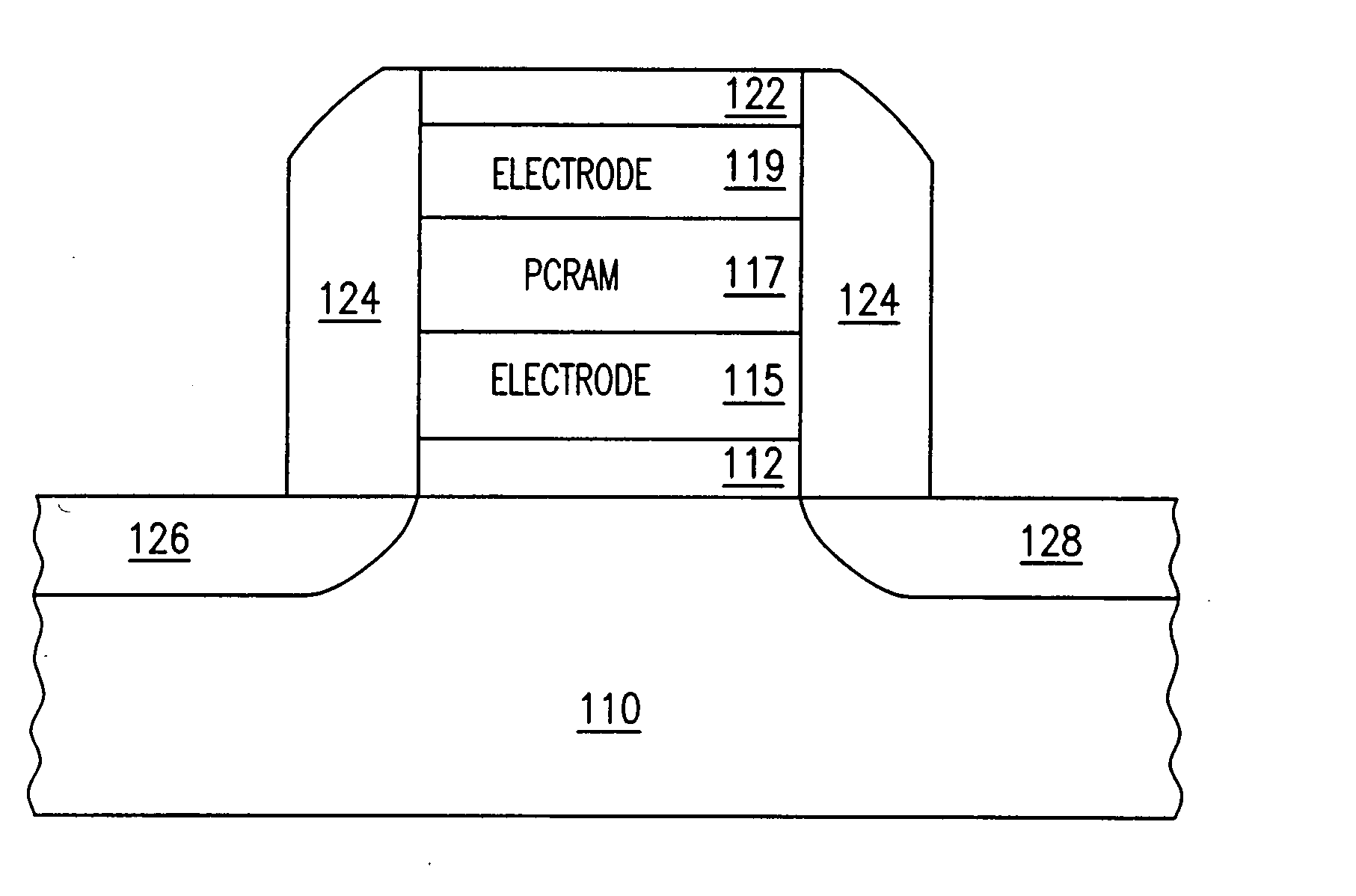
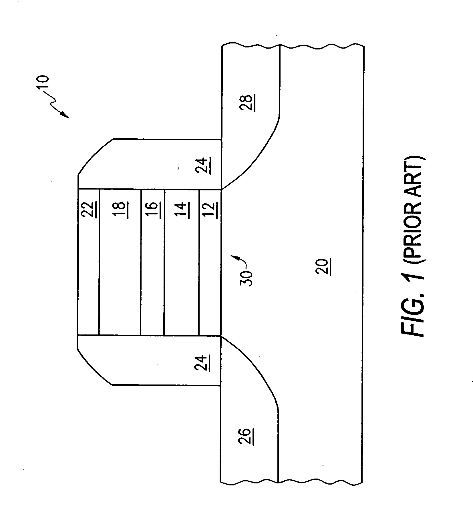
[0011] The present invention is directed to a flash memory cell in which the floating gate is implemented using a programmable conductance random access memory structure instead of the traditional polysilicon layer. Instead of storing or removing electrons from a polysilicon layer, the programmable conductance is switched between its low and high resistive states to operate the cell. The resulting cell can be erased faster and has better endurance (i.e., can withstand a greater number of erase / write cycles) than a conventional flash memory.

Problems solved by technology

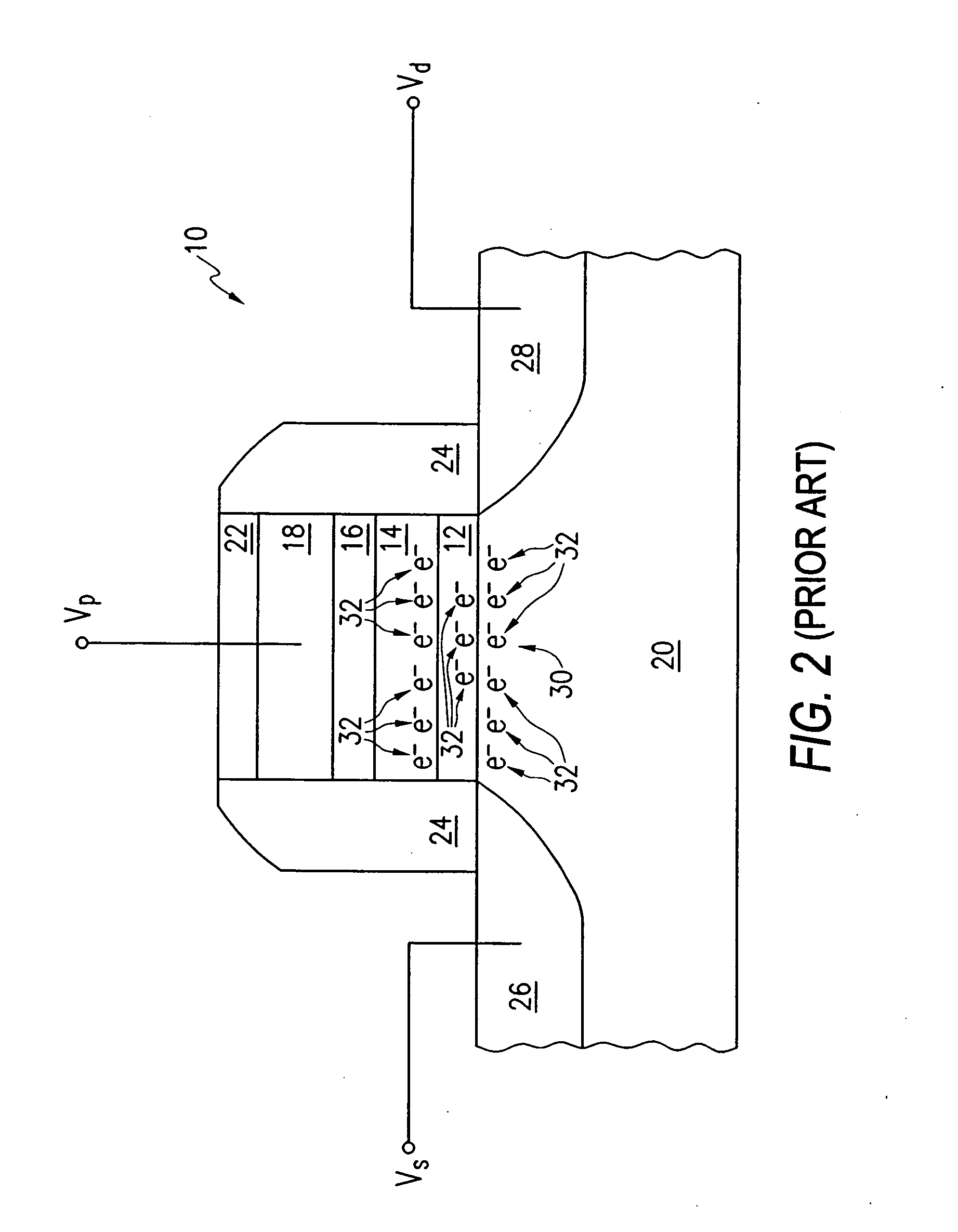
The erase operation requires high voltages and is relatively slow.
The high erase voltages are a fundamental problem arising from the high electron affinity of bulk silicon or large grain polysilicon particles used as the floating gate.
This creates a very high tunneling barrier.
This results in long erase times since the net flux of electrons leaving the gate is low.
In addition, other phenomena result as a consequence of this very high negative voltage.
Hole injection into the oxide is experienced which can result in erratic over erase, damage to the gate oxide itself, and the introduction of trapping states.

Method used


Image

  • Non-volatile memory structure
  • Non-volatile memory structure
  • Non-volatile memory structure

Examples


Embodiment Construction

[0021] In the following detailed description, reference is made to the accompanying drawings, which form a part hereof, and in which is shown by way, of illustration of specific embodiments in which the invention may be practiced. It is to be understood that other embodiments may be utilized, and that structural, logical and electrical changes may be made without departing from the spirit and scope of the present invention.

[0022] The terms “wafer” and “substrate” are to be understood as including silicon, silicon-on-insulator (SOI) or silicon-on-sapphire (SOS) technology, doped and undoped semiconductors, epitaxial layers of silicon supported by a base semiconductor foundation, and other semiconductor structures. Furthermore, when reference is made to a “wafer” or “substrate” in the following description, previous process steps may have been utilized to form regions or junctions in the base semiconductor structure or foundation. In addition, the semiconductor need not be silicon-ba...


PUM


Abstract

A non-volatile memory cell utilizes a programmable conductor random access memory (PCRAM) structure instead of a polysilicon layer for a floating gate. Instead of storing or removing electrons from a floating gate, the programmable conductor is switched between its low and high resistive states to operate the flash memory cell. The resulting cell can be erased faster and has better endurance than a conventional flash memory cell.

Description

FIELD OF THE INVENTION [0001] The present invention relates to the field of semiconductor memory devices and, more particularly, to a flash memory device. BACKGROUND OF THE INVENTION [0002] A nonvolatile memory is a type of memory that retains stored data when power is removed. There are various types of nonvolatile memories including e.g., read only memories (ROMs), erasable programmable read only memories (EPROMs), and electrically erasable programmable read only memories (EEPROMs), and flash memory. [0003] Flash memory is often used where regular access to the data stored in the memory device is desired, but where such data is seldom changed. For example, computers often use flash memory to store firmware (e.g., a personal computer's BIOS). Peripheral devices such as printers may store fonts and forms on flash memory. Wireless communications devices such as cellular and other wireless telephones use flash memory to store data and their operating systems. Portable electronics such...

Claims


Application Information

Patent Timeline
Patent Type & Authority Applications(United States)
IPC IPC(8): G11C13/02G11C16/02H01L29/68H01L45/00
CPCG11C13/0004H01L29/685G11C2213/53G11C13/0011
Inventor GILTON, TERRY L.
Owner ROUND ROCK RES LLC
Learn More