Automotive vehicle framing system

a technology for automotive framing and vehicle frame, which is applied in the direction of soldering apparatus, manufacturing tools,auxillary welding devices, etc., can solve the problems of affecting the accuracy of the overall framing system, affecting requiring high manufacturing costs. , to achieve the effect of maximizing the accessibility of welding robots, facilitating engagement and manipulation, and reducing the cost and additional footprint and volum

Active Publication Date: 2005-03-24
VALIANT CO LTD
View PDF20 Cites 29 Cited by
  • Summary
  • Abstract
  • Description
  • Claims
  • Application Information

AI Technical Summary

Benefits of technology

[0021] A primary advantage of the framing system of the present invention is that the robots are able to manipulate the tool arms so that a portion of one or more of the tool arms extend into the body preassembly and closely adjacent the body component reference surfaces. As such, relatively inexpensive clamping assemblies carried by each tool arm are employed to not only rapidly, but also accurately, position the vehicle body components together in preparation for final assembly. Since relatively simple clamping assemblies are used to position the vehicle body components, inaccuracies caused by wear and/or design of the previously known articulated clamps are avoided and welding robot accessibility is maximized.
[0022] A still further advantage of the automotive framing system of the present invention is that differ...

Problems solved by technology

All of these previously known automotive framing systems, however, suffer from a number of common disadvantages.
First, the wide area covered by the same tool structure, i.e. the gate or swing arm, does not enable a common approaching trajectory for the tool structure in which all the reference blocks and clamp units will remain stationary on the tool structure, and the clamps of simple design.
Since the clamping surfaces on the body components are frequently contained within the interior of the body preassembly, these previously known framing systems necessarily required complex, articulated clamping assemblies which must extend into the interior of the body preassembly in order to clamp the body components at their desired position relative to each other.
As such, these clamping assemblies are both expensive to manufacture and subject to wear after prolonged use.
Such wear adversely affects the accuracy of the overall framing system.
A still further disadvantage of these previously known framing systems is that, after the body preassembly has been moved into the assembly station and clamped at the desired position relative to each other, it is necessary for robotic welders to then extend through openings in either the g...

Method used


Image

  • Automotive vehicle framing system
  • Automotive vehicle framing system
  • Automotive vehicle framing system

Examples


Embodiment Construction

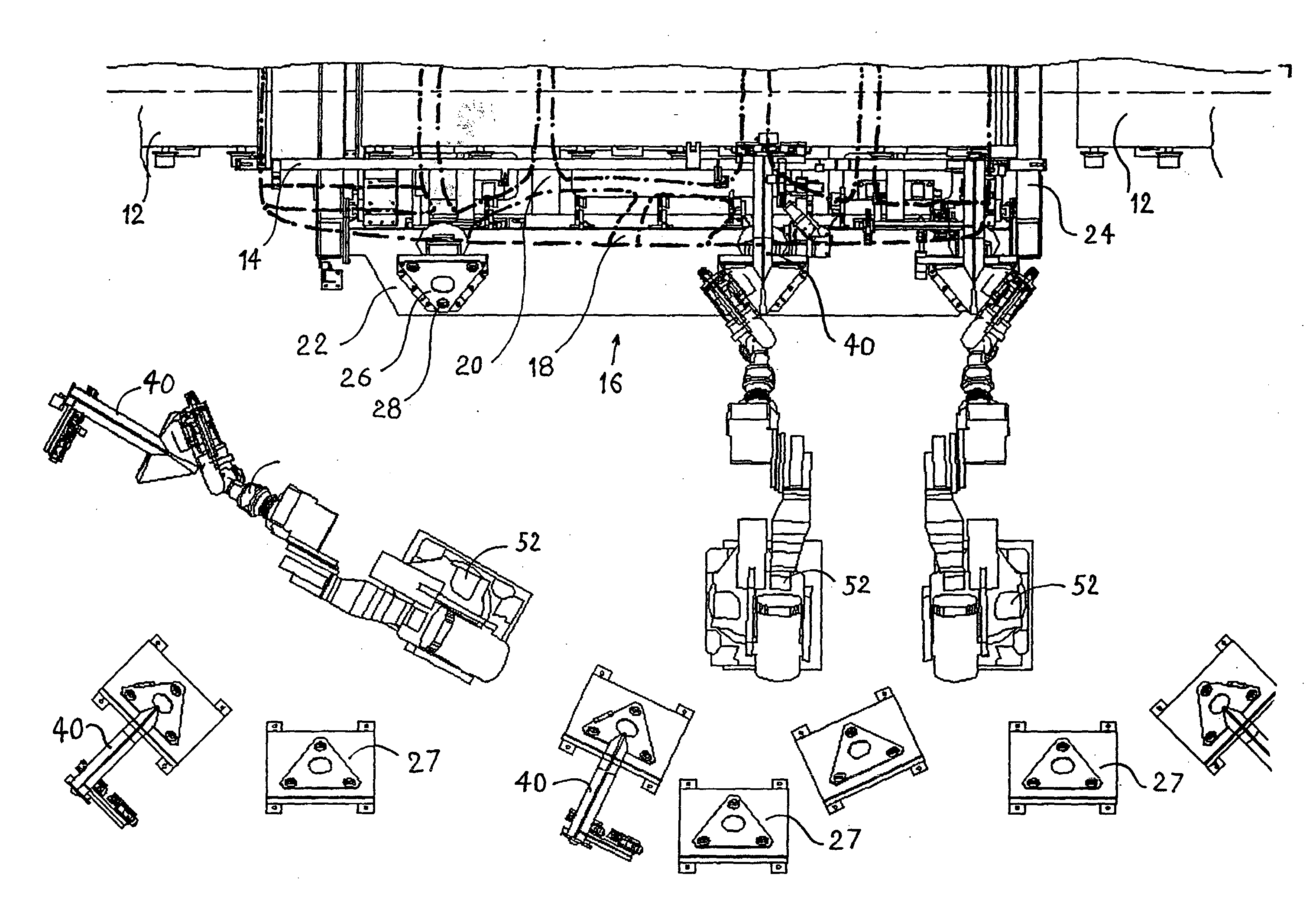
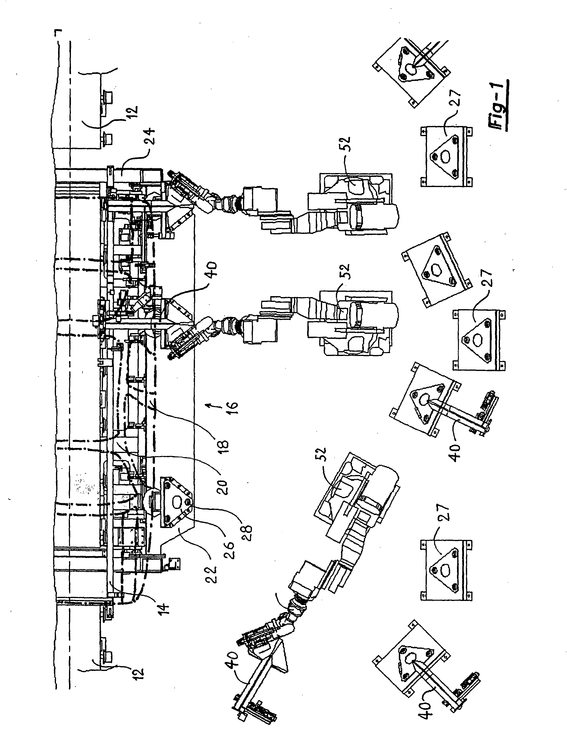
[0033] With reference first to FIG. 1, a preferred embodiment of the automotive framing system 10 of the present invention is shown for use with a manufacturing line for automotive vehicles. As used in this patent, the term “framing system” encompasses not only the vehicle frame of an automotive vehicle, but also any application where accurate positioning of two or more body components is desired. For example, such a framing system would also include fender setting, roof setting, door setting, as well as other vehicle body components than the vehicle frame. An elongated conveyor 12, illustrated only diagrammatically, sequentially conveys automotive body vehicle carriers 14 to an assembly station 16. Any conventional type of conveyor 12 may be utilized to convey the vehicle carrier 14 to the assembly station 16.

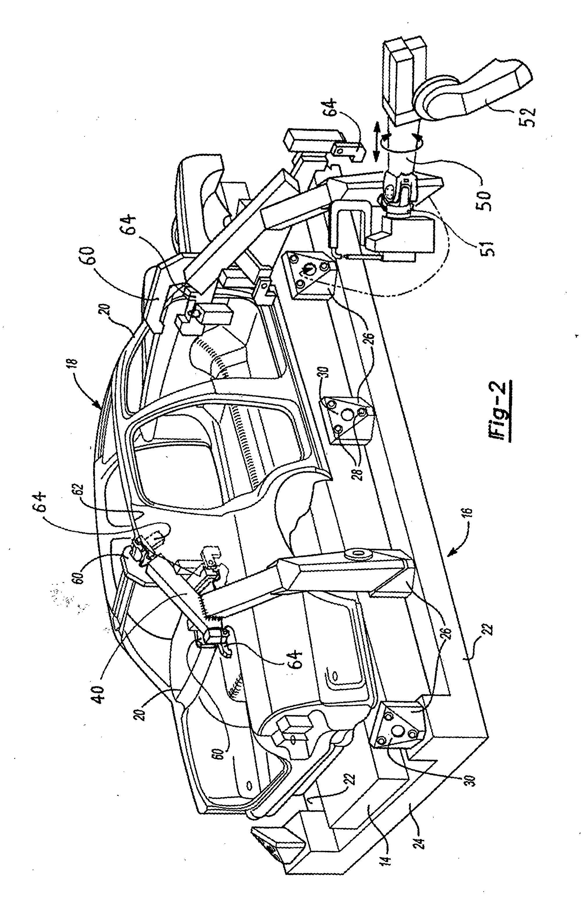
[0034] As best shown in FIG. 2, each vehicle body carrier 14 supports a body preassembly 18 comprising a plurality of body vehicle components 20. The body vehicle components ...


PUM

PropertyMeasurementUnit
Angleaaaaaaaaaa
Angleaaaaaaaaaa
Shapeaaaaaaaaaa

Abstract

A vehicle framing system for framing an automotive vehicle body from a plurality of separate body components wherein the body components each include a reference surface. The system includes an assembly station having spaced-apart frame members positioned so that, when a vehicle carrier supporting the vehicle body components is positioned at the assembly station, the frame members extend along opposite sides of the vehicle carrier. At least two docking stations are secured to each frame member at predetermined locations. A robot mounts its associated tool arm with a docking station. At least one set of reference block and framing clamp is secured to each tool arm and these framing clamps maintain the reference surfaces of the vehicle body components against the reference blocks to hold the vehicle components at a predetermined position relative to each other. After each robot positions each associated tool arm with the docking station, the robot disengages from the tool arm and then welds the body components together by a welding gun carried by the robots.

Description

BACKGROUND OF THE INVENTION [0001] I. Field of the Invention [0002] The present invention relates to an automotive framing system, or any other geometry station, for accurately positioning vehicle body components relative to each other prior to securing the vehicle body components together. [0003] II. Description of the Prior Art [0004] In the manufacture of automotive vehicles, a conveyor system typically transports a body preassembly sequentially along a conveyor line. Such body preassemblies supported by a vehicle carrier comprise various body components, such as an underbody, front structure, body sides, headers, etc., which are loosely attached to each other in their approximate final assembly position relative to each other. [0005] In order to fixedly secure the body components together, it is imperative that the body components be precisely positioned relative to each other to freeze their geometry by “tack welds” performed in this framing station, prior to a “respot” of the ...

Claims


Application Information

Patent Timeline
IPC IPC(8): B23K37/04B62D65/02
CPCB23K37/04Y10T403/59Y10T29/5168Y10T483/1714Y10T29/53417Y10T483/1726Y10T403/4677Y10T29/534Y10T29/5178Y10T403/4694Y10T29/49622Y10T403/22Y10T403/7094Y10T403/599Y10T29/49829Y10T29/49828Y10T29/53048Y10T29/53365Y10T29/53383Y10T403/593B62D65/02
Inventor BAULIER, DOMINIQUE
Owner VALIANT CO LTD
Why Eureka
Try Eureka