Particle retaining equipment

Active Publication Date: 2020-08-20
HALDOR TOPSOE AS
View PDF0 Cites 0 Cited by
  • Summary
  • Abstract
  • Description
  • Claims
  • Application Information

AI Technical Summary

Benefits of technology

[0024]3. As a further aspect of the invention, the wall of the particulate retaining chamber may be permeable to the fluid, but not to the particulate. Various technologies may ensure the correct permeability, for example a vee-wire of the correct mesh, or a grading particles encased in a mesh cage. Enhancing the wall of the particulate retaining chamber with a permeable surface is of particular interest when the fluid fed to the reactor may change state from liquid to gas and vice-versa (for example during start-up and shut down of a naphtha hydroprocessing unit). When the fluid is in liquid state, it would percolate by gravity through the lower part (for example the floor, if the particulate retaining chamber has a flat floor) of the particulate retaining chamber. If the permeable

Problems solved by technology

In other cases the presence of particles is unintentional.
However, in certain processes, the problem may appear or become more severe over time, for example when erosion and corrosion are involved.
Sometimes, installing a particle removing equipment as an independent unit operation prior to sensitive equipment is not possible in practice.
This create obstruction to the passage of the process fluids and therefore increases the pressure drop across the reactor bed.
On-stream collection of the particles is typically not available.
Such analyses are affected by large uncertainties due to particle agglomeration and oxidation.
Similarly, process gas resulting from the regeneration of FCC (fluid catalytic cracking) catalyst is often laden with catalyst particles and catalyst debris.
These are

Method used


Image

  • Particle retaining equipment
  • Particle retaining equipment
  • Particle retaining equipment

Examples


Embodiment Construction

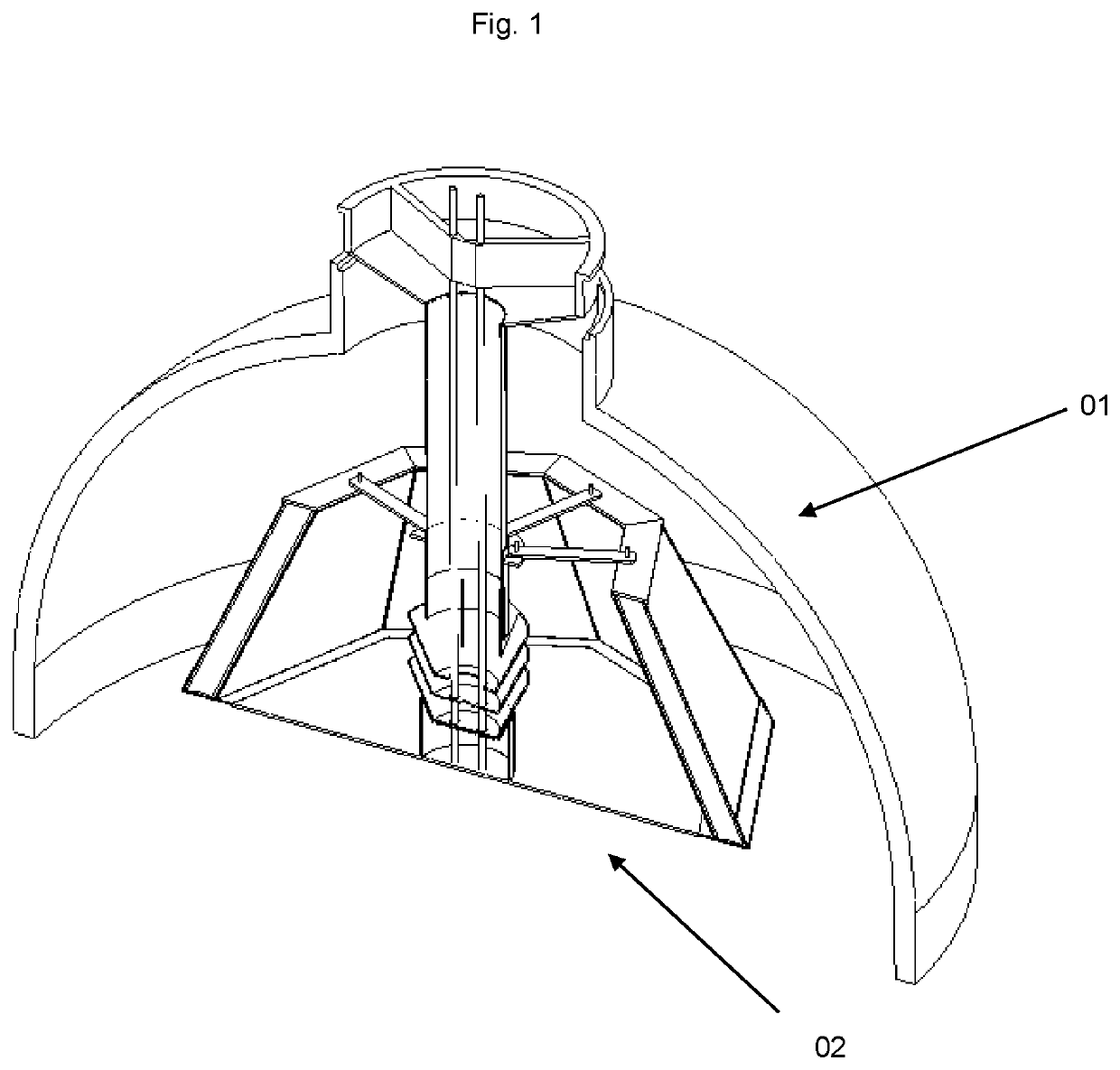
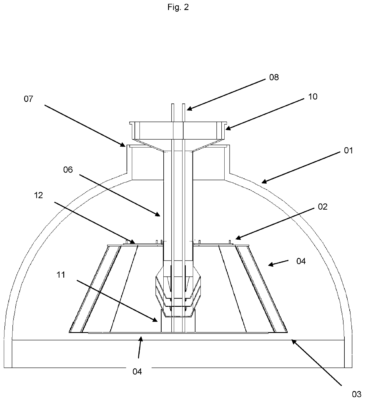
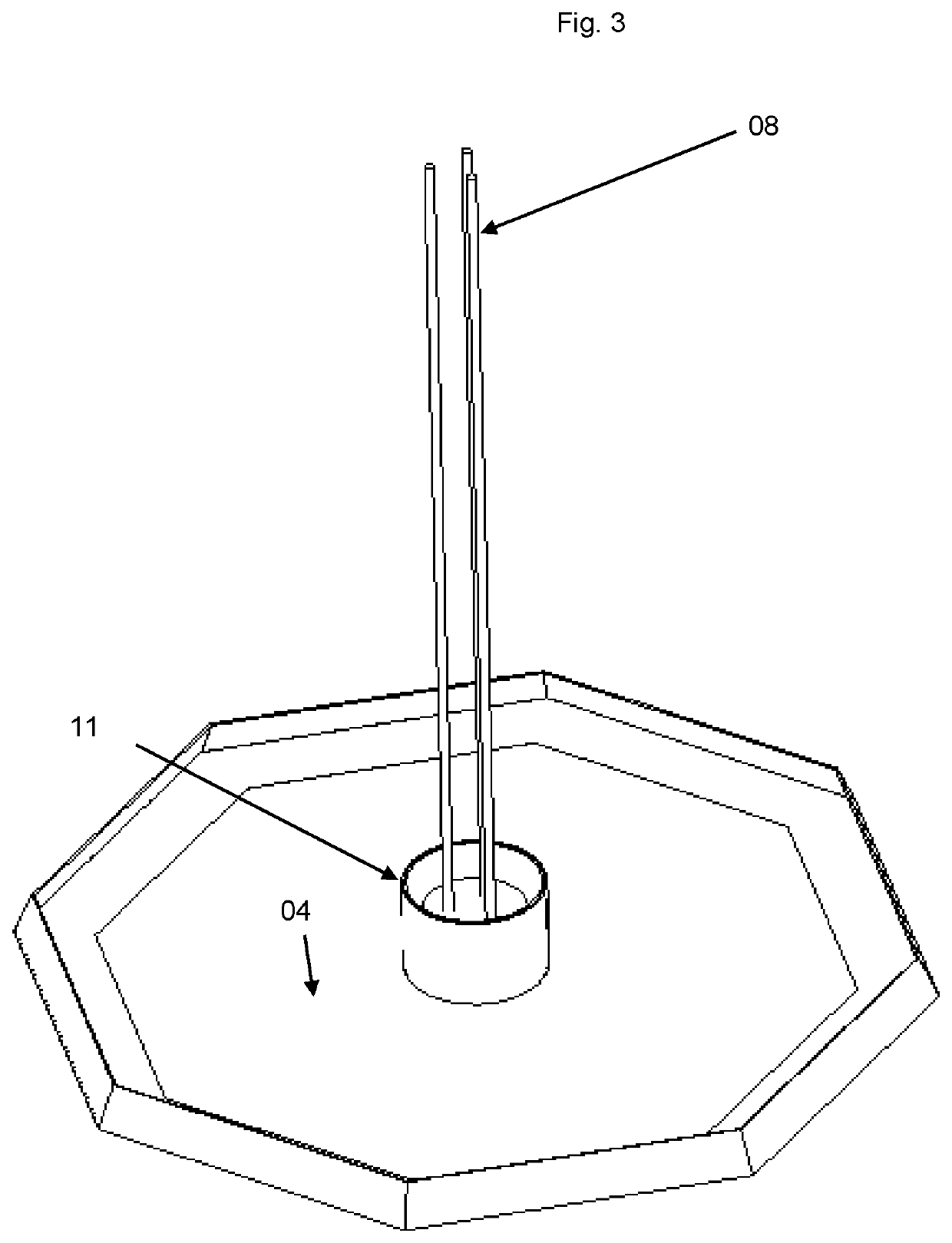
[0056]1) A particulate retaining equipment separating particulate from a fluid by settling operate as shown in FIG. 10. The peripheral wall of the particulate retaining chamber is bent towards the diffusing pipe such to fit in the reactor head. The open section between the upper end of the peripheral wall of the particulate retaining chamber and the diffusing pipe may be a parameter of design to achieve certain flow patterns inside the particulate retaining chamber.

[0057]The fluid and the particles flow inside the diffusing pipe. The openings of the diffusing pipes are such to impart to the mixture a motion upwards at the outlet of the diffusing pipe. The motion of the fluid is represented by the continuous line. From the outlet of the diffusing pipe, the fluid continues its motion upwards. Once it has reached the upper end of the wall of the particulate retaining chamber, the fluid exits the particulate retaining equipment. The lines of motion bend downward, and the fluid leaves th...


PUM


Abstract

A means for retaining particulate matter, for use in process equipment operated with a fluid, including: a particle retention chamber, a means of suspension, a means of fastening, a support, wherein the particle retention chamber is configured to be suspended from the support by the means of suspension; the means of fastening is configured to fasten the means of suspension to the support.

Description

FIELD OF THE INVENTION[0001]This invention relates to a process equipment with particle separation. More specifically the invention relates to process equipment which does not comprise means for supporting equipment below the inlet diffuser. The process equipment can be a down-flow catalytic reactor which includes vertically superimposed packed beds of particulate catalytic material. This type of reactor is used in the petroleum and chemical processing industries for carrying out various catalytic reactions, such as sulphur and nitrogen conversion (hydrodesulphurization and hydrodenitrification—HDS / HDN); hydrogenation of: olefins (HYD) and aromatics (hydrodearomatisation—HDA), metals removal (hydrodemetallisation—HDM), oxygen conversion (hydrodeoxygenation—HDO) and hydrocracking (HC). The reactor is a radial converter, where elements of the decks have to be fixed to the reactor. This reactor has a radial flow crossing a packed bed of catalytic material and it is typically used in th...

Claims


Application Information

Patent Timeline
IPC IPC(8): B01J8/00
CPCB01J2208/00769B01J8/006B01J8/007B01J8/0492B01J4/002B01J4/005B01J8/0065B01J8/0085B01J8/0278B01J2208/00902B01J2219/00247
Inventor ZAHIROVIC, EMIRMORTON, DANIELROGATO, MARCNIELSEN, FLEMMING PLOUGSTRUP
Owner HALDOR TOPSOE AS
Why Eureka
Try Eureka