Turbomachine with low noise emissions for aircraft

a technology of turbines and turbine blades, applied in the field of turbines, can solve the problems of large noise generation of fans, noise emissions that can be very harmful to the environment, and aircraft noise, and achieve the effect of reducing the noise of jets

Active Publication Date: 2005-03-24
SN DETUDE & DE CONSTR DE MOTEURS DAVIATION S N E C M A
View PDF11 Cites 79 Cited by
  • Summary
  • Abstract
  • Description
  • Claims
  • Application Information

AI Technical Summary

Benefits of technology

[0019] More precisely, the object of the invention is to present a turbomachine for an aircraft with an architecture that reduces noise emissions produced compared with noise emissions encountered with embodiments according to prior art.
[0034] Thus, the turbomachine proposed in this second preferred embodiment firstly reduces the noise from the jets and the combustion chamber as indicated above, and also minimises fan noise due to the use of these counter rotating fans with noise reduction effects known to those skilled in the art.

Problems solved by technology

This conventional type of turbomachine architecture causes noise emissions that can be very harmful to the environment, particularly when an aircraft fitted with this type of turbomachine is close to an airport.
The first of these three noise sources is the fan that generates large amounts of noise, largely due to aerodynamic shocks developed around the outer part of the blades of this fan which turn at a very high speed.
Furthermore, noise emissions also originate from the combustion chamber which forms an integral part of the turbomachine gas generator.
Finally, the third main source of noise emissions consists of jets escaping from the turbomachine.
Noise caused by hot gases and secondary air output from the turbomachine is then added to noise generated by hot gases, which is usually preponderant due to the higher hot gas ejection velocity.
However, this type of architecture considerably increases the length of the turbomachine, due to the addition of a mixer with sufficiently large dimensions to be capable of mixing sufficiently to significantly reduce jet noise.
Consequently, all these modifications directly cause an unwanted increase in the global mass and dimensions of the turbomachine.
Nevertheless, although this solution is globally satisfactory in terms of reducing fan noise, it has absolutely no effect on jet noise or combustion chamber noise, although combustion chamber noise constitutes a very significant part of the global emissions of noise generated by the turbomachine.

Method used


Image

  • Turbomachine with low noise emissions for aircraft
  • Turbomachine with low noise emissions for aircraft
  • Turbomachine with low noise emissions for aircraft

Examples


Embodiment Construction

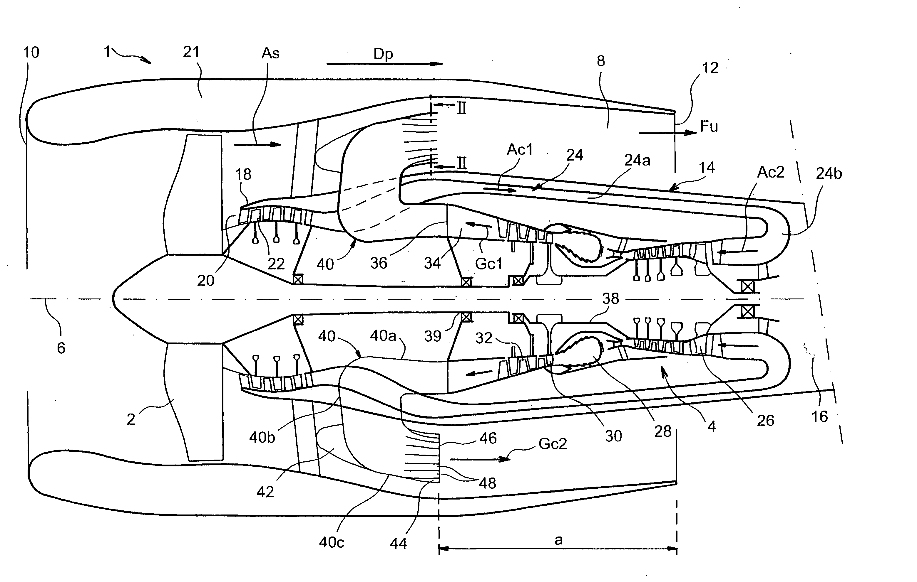
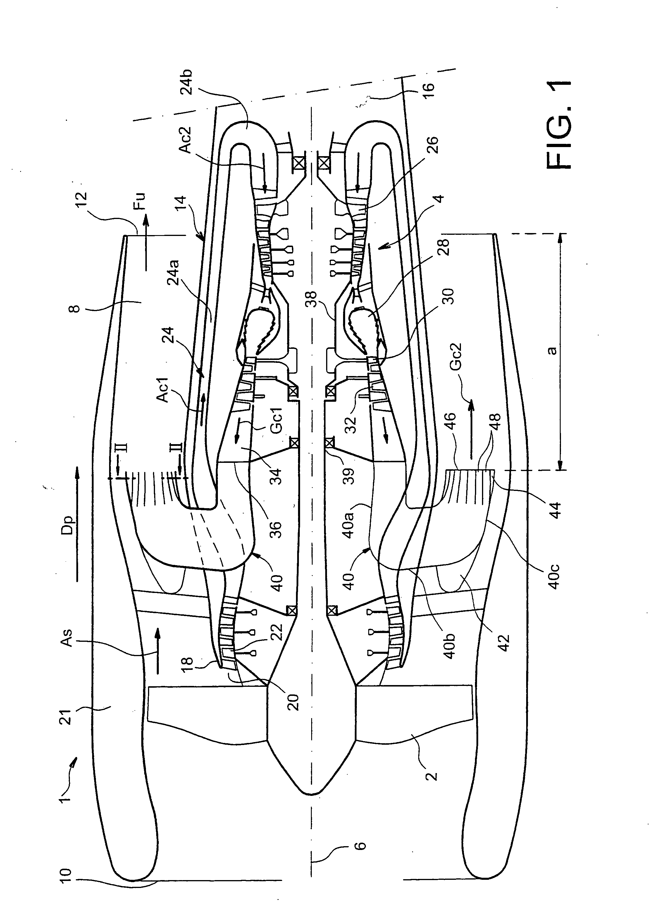
[0045]FIG. 1 shows a turbomachine 1 for an aircraft according to a first preferred embodiment of this invention.

[0046] The turbomachine 1 comprises a single conventional fan 2 driven by a twin shaft type gas generator 4 arranged on the downstream side of this fan 2.

[0047] The turbomachine 1 with its main longitudinal axis 6 has an annular fan duct 8 which extends between an input 10 on the front of the turbomachine 1 and close to the fan 2, as far as an output 12 located further towards the downstream side.

[0048] The inner part of the annular fan duct 8 is delimited by a noise suppression structure 14 surrounding the gas generator 4, this structure 14 particularly forming the ogive-shaped closed back 16 of the turbomachine 1. Moreover, the noise suppression structure 14 is provided with an open front part 18 close to the fan 2 and on its downstream side, this open front part 18 delimiting the outer part of an annular input 20 to the gas generator 4. Furthermore, the annular fan d...


PUM


Abstract

The invention relates to a turbomachine (1) for an aircraft comprising a gas generator (4) designed such that hot gases are ejected from a combustion chamber (28) towards the upstream side of the turbomachine, and also comprising a plurality of hollow mixer struts (40) connected to an output (36) from the gas generator through which hot gases can pass, each mixer strut comprising an output mixer portion (40c) located inside the annular fan duct (8) so as to mix the secondary air and the hot gases ejected by these output mixer portions towards the downstream side of the turbomachine.

Description

TECHNICAL FIELD [0001] This invention relates generally to a turbomachine for the propulsion of an aircraft, and more particularly a turbomachine with a design capable of reducing noise emissions produced by this turbomachine. STATE OF PRIOR ART [0002] Typically, an aircraft turbomachine has a fan driven by a gas generator that may for example be of the single-shaft, twin-shaft, or three-shaft type. [0003] For example, a gas stream passes through all components of the gas generator from the upstream side towards the downstream side of the turbomachine, namely along a main direction of the gas stream through the turbomachine. [0004] This conventional type of turbomachine architecture causes noise emissions that can be very harmful to the environment, particularly when an aircraft fitted with this type of turbomachine is close to an airport. [0005] Three main noise sources cause these emissions. [0006] The first of these three noise sources is the fan that generates large amounts of n...

Claims


Application Information

Patent Timeline
Patent Type & Authority Applications(United States)
IPC IPC(8): F02K3/06F02K3/105
CPCF02K1/48F02K3/06F05D2260/96Y02T50/671F02K3/105Y02T50/60F02K3/04F02K3/068F02K3/072
Inventor LARDELLIER, ALAIN
Owner SN DETUDE & DE CONSTR DE MOTEURS DAVIATION S N E C M A
Why Eureka
Try Eureka