Eureka AIR delivers breakthrough ideas for toughest innovation challenges, trusted by R&D personnel around the world.

Iron core and method of manufacturing the same and apparatus for manufacturing the same

a technology of iron core and rotary machine, which is applied in the direction of dynamo-electric machines, electrical equipment, magnetic circuit shapes/forms/construction, etc., can solve the problems of difficult to guarantee the inability to uniformize and the difficulty in ensuring the accuracy of the post-process curvature of the strip after the mill roll process. to achieve the effect of high-accur

Active Publication Date: 2005-03-24
HITACHI ASTEMO LTD
View PDF9 Cites 7 Cited by
  • Summary
  • Abstract
  • Description
  • Claims
  • Application Information

AI Technical Summary

Benefits of technology

[0009] The present invention is applied an iron core for an electric rotary machine manufactured by forming a strip into a spirally laminated structure through a rolling-bending process. The object of the invention is to make high-accuracy manufacturing of the iron core possible even if the strip has thickness variations.

Problems solved by technology

Even when the amount of rolling is held uniform, however, the post-process curvature of the strip will not be uniform if the strip has thickness variations.
If the variations in the thickness of the strip are large, however, it is difficult to guarantee the accuracy of the curvature of the strip.
In the example disclosed in Japanese Patent Laid-Open No. 2000-224817, although providing the member for restricting the narrowing down of the strip in a widthwise direction, if the strip has thickness variations, it is extremely difficult to guarantee the accuracy of the post-process curvature of the strip after the mill roll process.

Method used


Image

  • Iron core and method of manufacturing the same and apparatus for manufacturing the same
  • Iron core and method of manufacturing the same and apparatus for manufacturing the same
  • Iron core and method of manufacturing the same and apparatus for manufacturing the same

Examples


Embodiment Construction

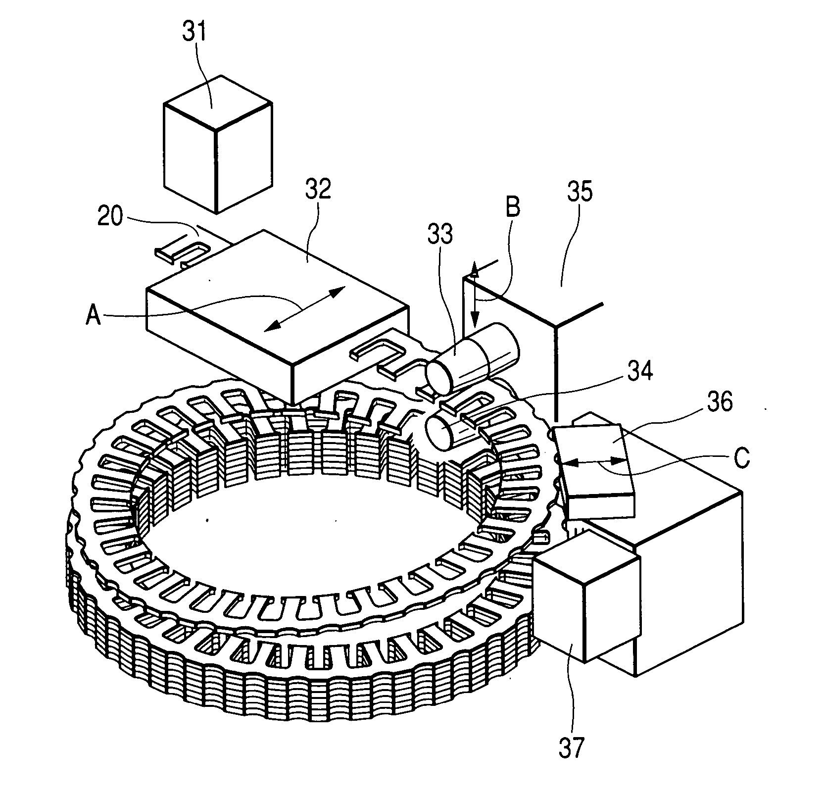
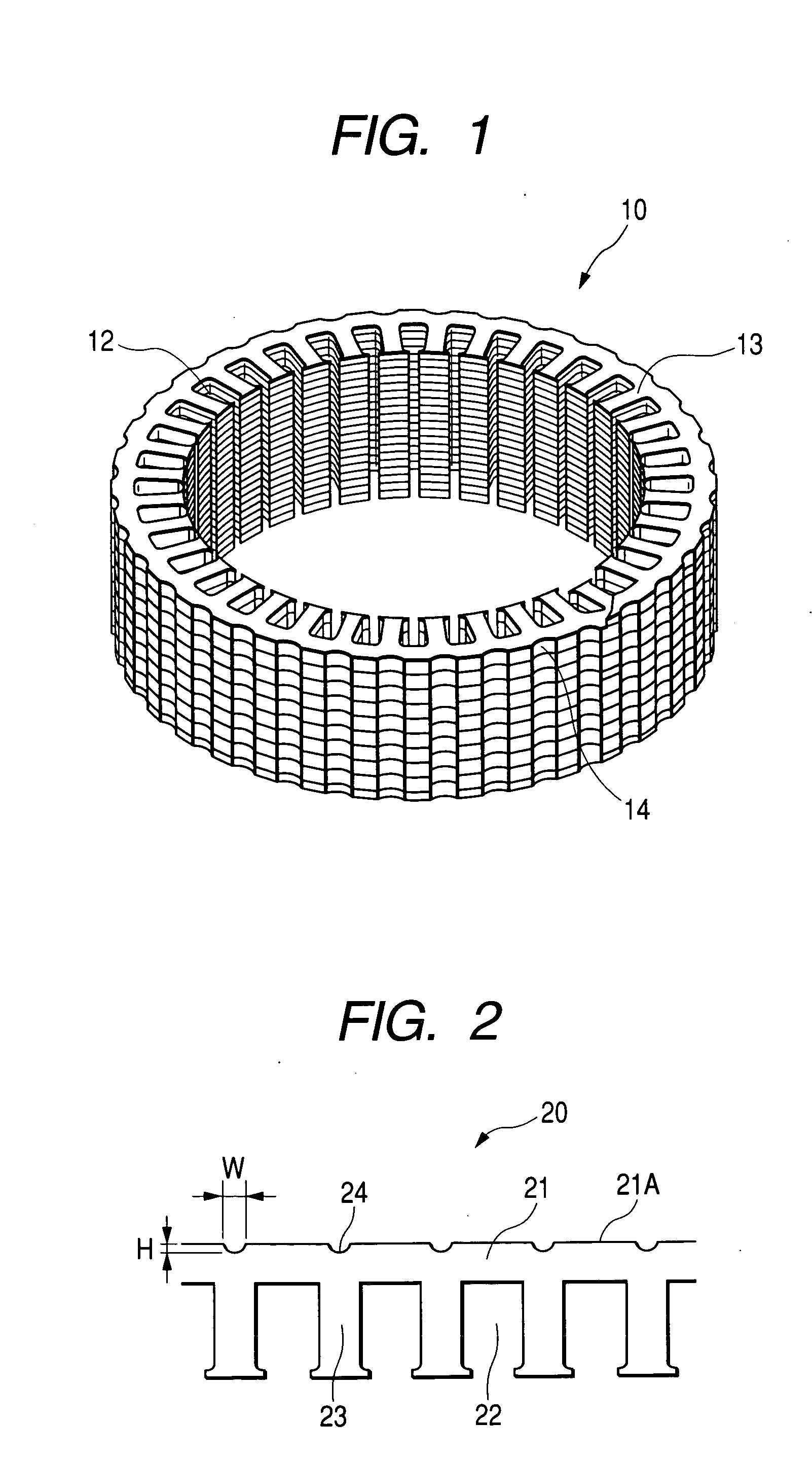
[0022]FIG. 1 is a view showing the outer appearance of an iron core for an electric rotary machine according to the present invention. An iron core 10 is formed into a ring-shaped configuration by shaping a strip (band-like thin plate) as an intermediate product of the iron core into a spirally laminated structure through a rolling-bending process. On the inner circumferential side of the iron core 10, a plurality of slots 12 and a plurality of teeth 13 for the insertion of winding wires as coil elements are alternately formed. For example, the total of thirty-six slots 12 are formed with a 10° pitch in a circumferential direction, while the total of thirty-six teeth 13 are formed with a 10° pitch in a circumferential direction.

[0023] In accordance with the present invention, the outer periphery of the iron core 10 is provided with notches 14 spreading in the axial direction of the core at regular intervals in the circumferential direction. Preferably, the notches 14 are arranged i...


PUM

PropertyMeasurementUnit
thicknessaaaaaaaaaa
widthaaaaaaaaaa
widthaaaaaaaaaa

Abstract

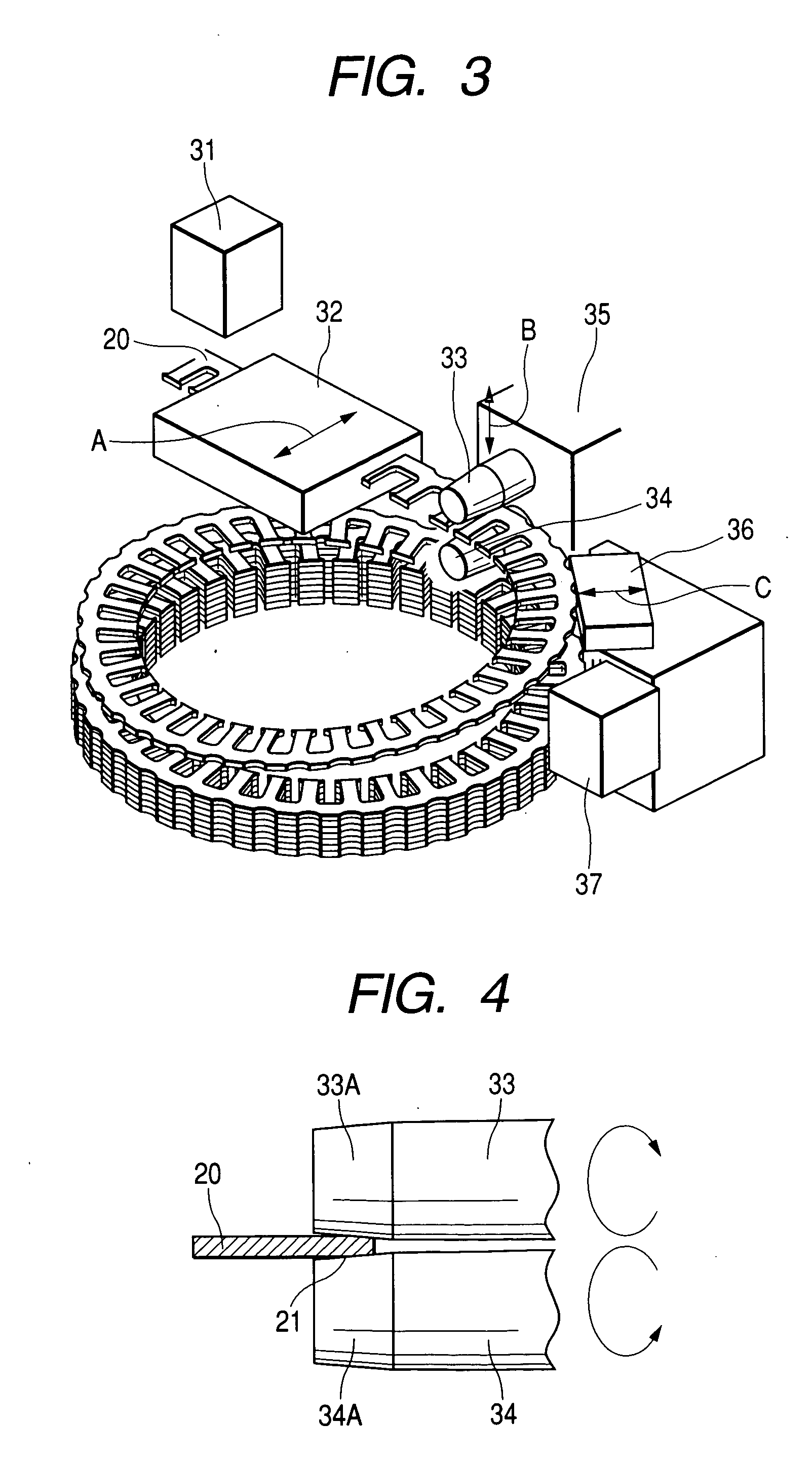
An apparatus for manufacturing an iron core comprising: a plate thickness measurement unit for measuring a thickness of the strip as an intermediate product of the iron core; an inlet guide for positioning the strip in a widthwise direction thereof; a mil roll unit for performing a rolling-bending process to the strip fed out of the inlet guide; a restraint jig for shaping the strip fed out of the mil unit and holding a curvature thereof constant; and a curvature measurement unit for measuring a curvature of the strip to which the rolling-bending process has been performed by using said mill roll. Position control of the inlet guide, the pressure roll unit, and the restraint jig is performed based on at least one of the plate thickness and the curvature of the strip.

Description

[0001] The present application claims priority from Japanese application serial no. 2003-326557, filed on Sep. 18, 2003), the content of which is hereby incorporated by reference into FIELD OF THE INVENTION [0002] The present invention relates to an iron core for an electric rotary machine such as a motor and, more particularly, to an iron core manufactured by forming a strip (band-like plate) into a spirally laminated structure through a rolling-bending process, to a method of manufacturing the same, and to an apparatus for manufacturing the same. BACKGROUND OF THE INVENTION [0003] In the electric rotary machine such as a motor, a method of manufacturing the iron core by forming a strip into a spirally laminated structure through a rolling-bending process is well known. In such a manufacturing method, the strip is bent into a spiral configuration by rolling one edge thereof with a mill roll. In other words, the strip is rolled by the mill roll so as to thin toward the outer circumf...

Claims


Application Information

Patent Timeline
Patent Type & Authority Applications(United States)
IPC IPC(8): H02K1/16H02K15/02
CPCH02K1/16H02K15/026Y10T29/49991Y10T29/49771Y10T29/49906Y10T29/49078Y10T29/53526Y10T29/5317
Inventor KOSHIZAKA, ATSUSHIUEDA, TOSHIAKIKIRIHARA, YUICHIKAWAHARA, KEIJISASAKI, SUSUMU
Owner HITACHI ASTEMO LTD
Why Eureka
Eureka Blog
Learn More