Liquid material delivering method and device therefor

a liquid material and delivering method technology, applied in the direction of positive displacement liquid engines, liquid fuel engines, packaging goods types, etc., can solve the problems of dripping and ejection, liquid material may leak through the seal portion, and the smooth sliding of the plunger is impeded, so as to achieve accurate delivery and dripping and ejection

Inactive Publication Date: 2005-03-24
MUSASHI ENG INC
View PDF9 Cites 9 Cited by
  • Summary
  • Abstract
  • Description
  • Claims
  • Application Information

AI Technical Summary

Benefits of technology

[0010] With the view of solving the problems set forth above, an object of the present invention is to provide a method and a device for accurate delivery, dripping and ejection in the form of flying droplets. Another object of the present invention is to provide a liquid delivering method and device, which can effectively purge out air bubbled trapped in a liquid material, and can utilize the liquid material, which is discharged in a mixed state together with a group of air bubbles during the air bubble purging operation, again for delivery, dripping and ejection in the form of flying droplets without wasting the liquid material.

Problems solved by technology

As a result, smooth sliding of the plunger is impeded and the liquid material cannot be delivered in a fixed amount.
In addition, the liquid material may leak through the seal portion and eventually fail to come out in some cases.
In a system requiring a sharp pressure rise, therefore, a factor of preventing the sharp pressure rise is resulted because a space uselessly occupied by the liquid material is increased.

Method used


Image

  • Liquid material delivering method and device therefor
  • Liquid material delivering method and device therefor
  • Liquid material delivering method and device therefor

Examples


embodiment 1

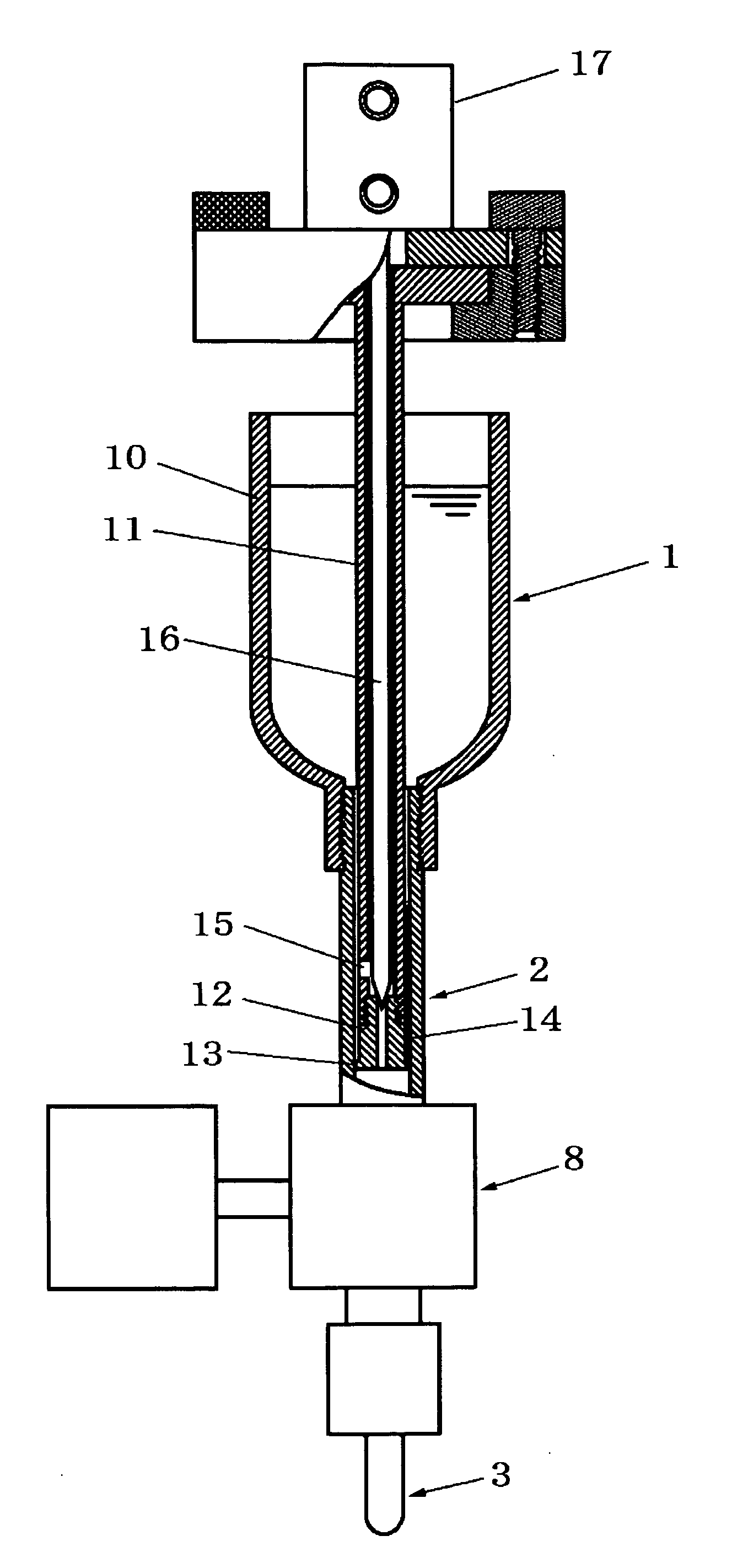
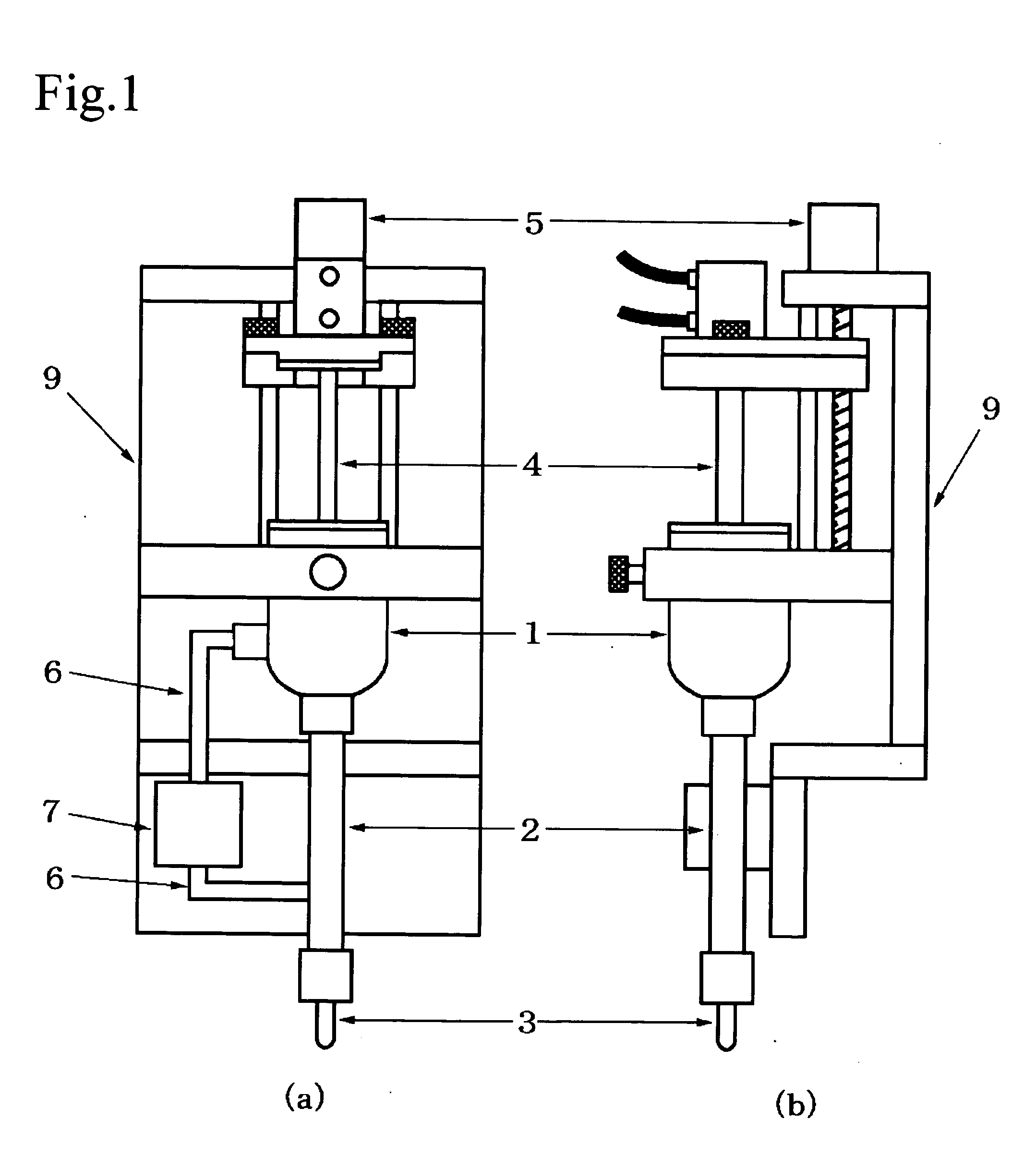
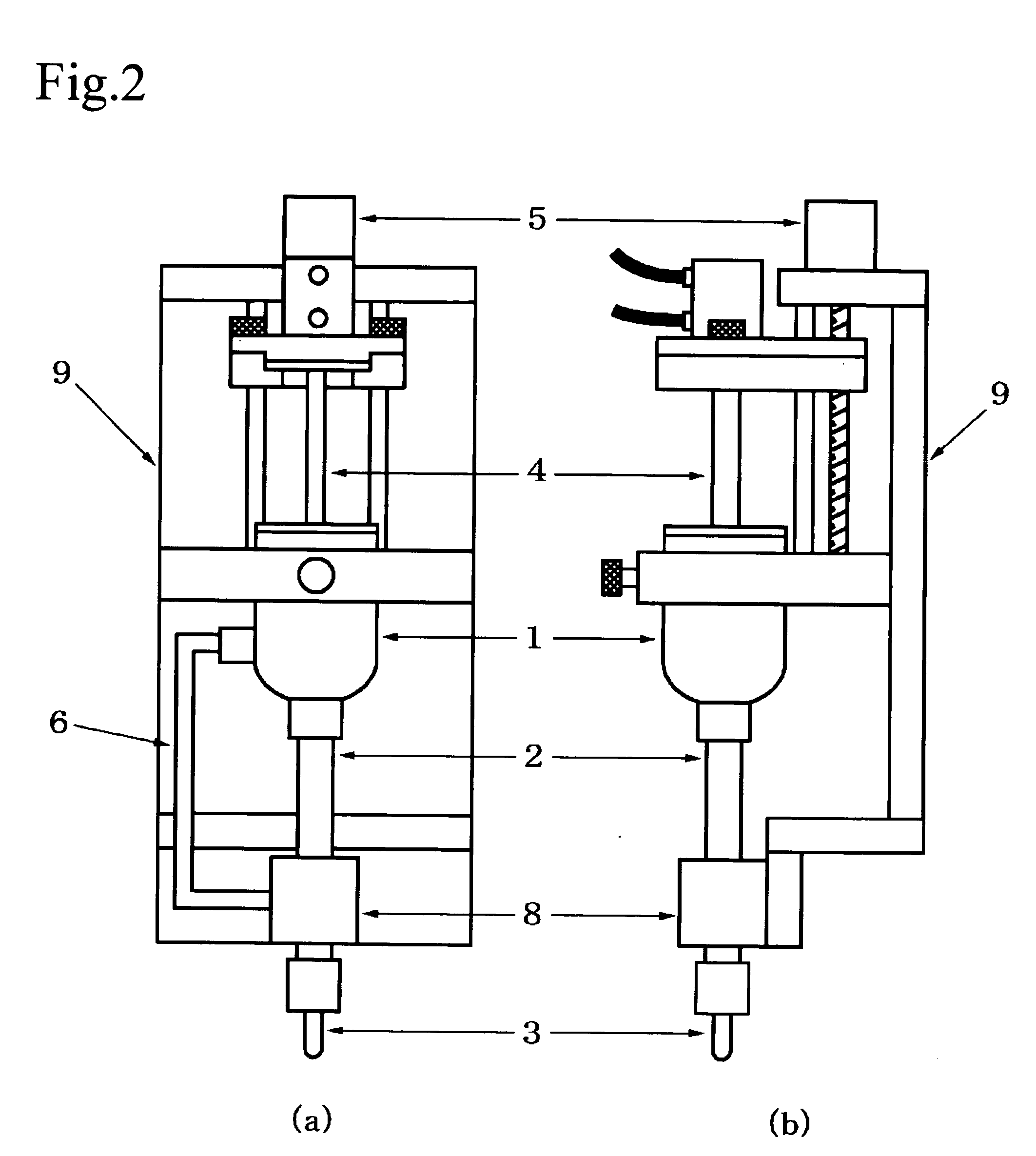
[0060] One embodiment of the present invention comprises, as shown in FIG. 1, a liquid material storage section 1 for storing a liquid material, a nozzle section 3 for delivering the liquid material, a liquid feed passageway 2 for establishing communication between the storage section and the nozzle section 3, a plunger section 4 having a seal portion sliding while closely contacting an inner surface of the liquid feed passageway 2, a plunger moving means 5 for advancing and retracting the plunger section 4, a liquid feed passageway 6 for establishing communication between the liquid material storage section 1 and a portion of the liquid feed passageway 2 near a nozzle-side distal end thereof, a liquid feed valve 7 disposed midway the liquid feed passageway 6, and a frame 9 for supporting the above-mentioned components.

[0061] The frame 9 comprises a guide rod for guiding a plunger support in the vertical direction, an upper frame for supporting a screw shaft to move the plunger sup...


PUM

PropertyMeasurementUnit
liquidaaaaaaaaaa
inner diameteraaaaaaaaaa
volumeaaaaaaaaaa

Abstract

A method and a device for accurate delivery, dripping and ejection in the form of flying droplets are provided.
A liquid material delivering method wherein a liquid material is pressurized by a plunger sliding while closely contacting an inner wall surface of a liquid feed passageway establishing communication between a nozzle and a storage section to deliver the liquid material through the nozzle. The plunger is disposed in a space filled with the liquid material. A sliding surface of the plunger section sliding while closely contacting the inner wall surface of the liquid feed passageway divides the space into a nozzle-side liquid material part and a storage container-side liquid material part. Of divided two parts of the liquid material, the liquid material in the nozzle-side liquid material part is delivered by the plunger section advancing in the liquid feed passageway. A liquid material delivering device comprises a liquid material storage section for storing a liquid material, a nozzle section for delivering the liquid material, a liquid feed passageway for establishing communication between the storage section and the nozzle section, a plunger section having a seal portion sliding while closely contacting an inner surface of the liquid feed passageway, and plunger moving means for advancing and retracting the plunger section. The delivering device further comprises another liquid feed passageway 2 for establishing communication between a portion of the aforesaid liquid feed passageway near a nozzle-side distal end thereof and a portion of the aforesaid liquid feed passageway near the liquid material storage section or the liquid material storage section itself, and a liquid feed valve disposed at a distal end of the another liquid feed passageway 2 or midway the another liquid feed passageway 2.

Description

TECHNICAL FIELD [0001] The present invention relates to the field in which a liquid material is pressurized by a plunger sliding while closely contacting an inner wall surface of a liquid feed passageway to deliver the liquid material through a nozzle. More particularly, the present invention relates to a liquid material delivering method and device, which can prevent undesired drying and sticking of the liquid material on the inner surface of the liquid feed passageway and undesired leakage of the liquid material from the plunger, can reduce the volume of a space in which the plunger is disposed to pressurize the liquid material, thereby ensuring accurate delivery, and can eliminate loss of the liquid material during the operation of purging air bubbles trapped in the liquid material, thereby realizing efficient of the liquid material. [0002] Herein, the term “delivery” means that the liquid material is delivered, dripped, or ejection in the form of flying droplets. BACKGROUND ART ...

Claims


Application Information

Patent Timeline
Patent Type & Authority Applications(United States)
IPC IPC(8): B05C5/00F04B53/06B05C5/02B05D1/26F04B13/00
CPCB05C5/0225B05C5/02B05C5/00B05D1/26
Inventor IKUSHIMA, KAZUMASA
Owner MUSASHI ENG INC
Why Eureka
Try Eureka