Line tensioning and coupling apparatus

a technology of coupling apparatus and tensioning line, which is applied in the direction of mechanical equipment, belts/chains/gearrings, waterborne vessels, etc., can solve the problems of difficulty in tying down a load on a cargo bed, a boat to the dock, and a bumper to the boat, and achieves the effect of reliable holding load, simple use, and low manufacturing cos

Inactive Publication Date: 2005-03-24
SHERMAN KEITH E +1
View PDF15 Cites 35 Cited by
  • Summary
  • Abstract
  • Description
  • Claims
  • Application Information

AI Technical Summary

Benefits of technology

[0006] A feature of this invention is a light weight, relatively small planar member that has opposing top slots, a first aperture and a second aperture and a plurality of oriented slots on opposite sides for wrapping the line around the apparatus and through the slots. These plurality of slots have right angled faces that are formed on opposite surfaces of each of the slots while the remaining portion of where the line or rope is wrapped or inserted is formed with radius or may otherwise be beveled.
[0007] A feature of this invention is that the planar tensioning / coupling body is made from a non-corrosive material that floats and is characterized as being simple to use, inexpensive to manufacture and reliable to hold the load without slippage.

Problems solved by technology

As one skilled in this technology readily realizes, it is often difficult to tie an object like a boat to the dock, or a bumper to a boat or tie down a load on a cargo bed and be able to apply tension when attempting to knot the rope or line together.

Method used


Image

  • Line tensioning and coupling apparatus
  • Line tensioning and coupling apparatus
  • Line tensioning and coupling apparatus

Examples


Embodiment Construction

[0017] While the preferred embodiment described a particular configuration, dimensions and material, as one skilled in the art these parameters can be changed without changing the scope of this invention, unless a particular configuration or dimension is specified as not capable of being modified. For example, the unit is made in the preferred embodiment as being sufficiently small to be hand-held. Obviously, it can take any size which would be predicated by the particular application to which it is being utilized. As used herein the terms line, rope, braid, cable and the like are synonymous and connote the same meaning and function.

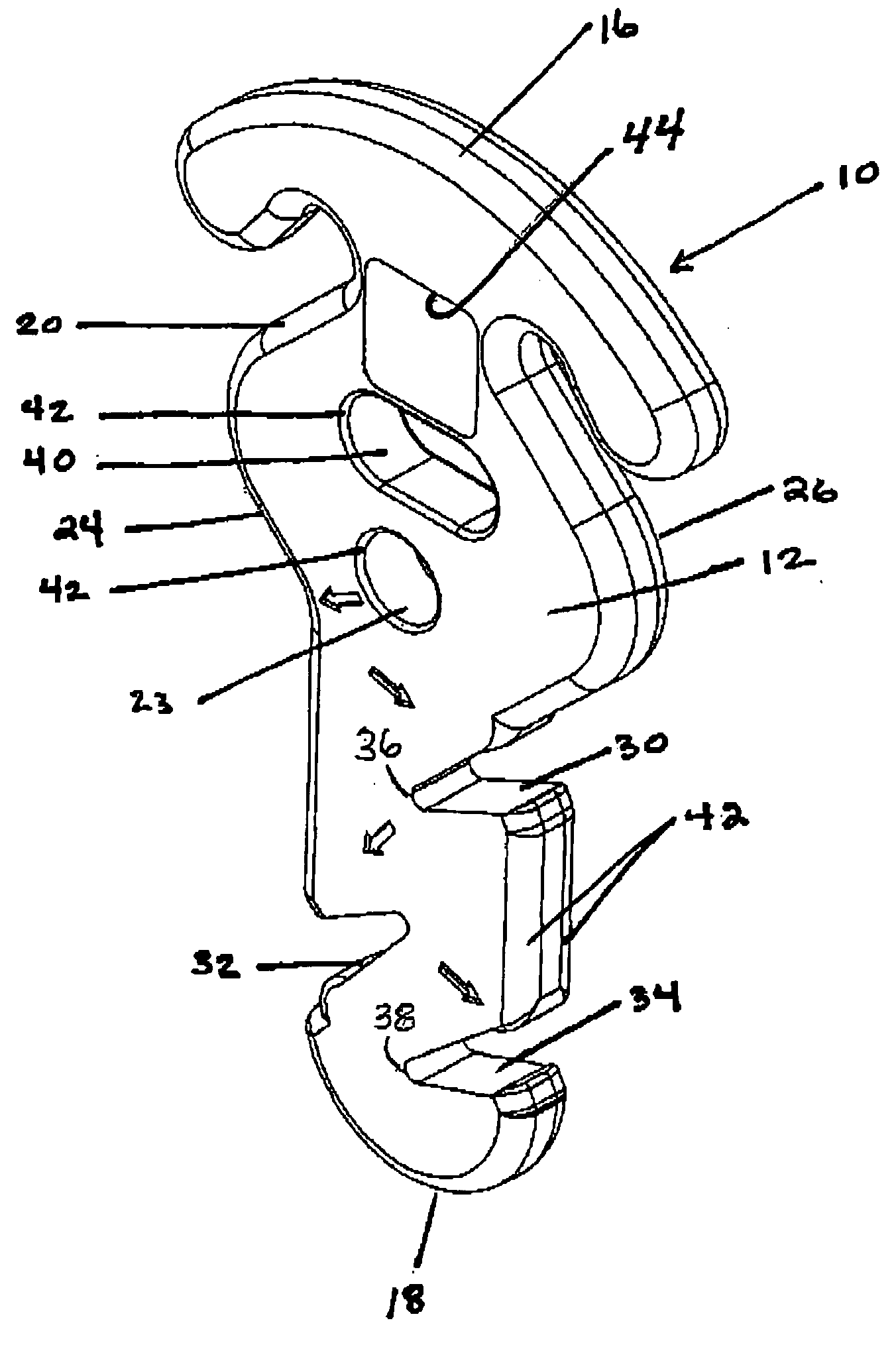
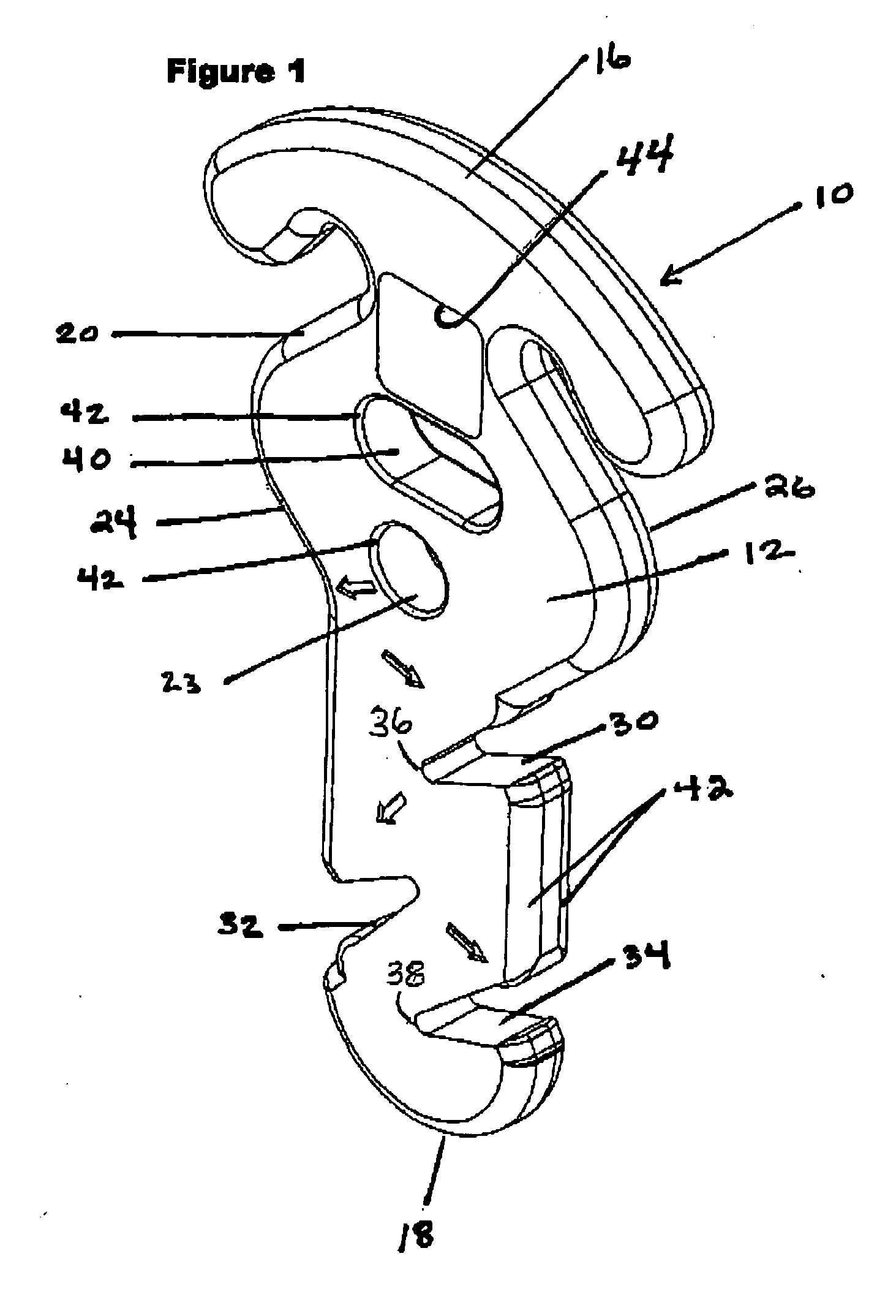
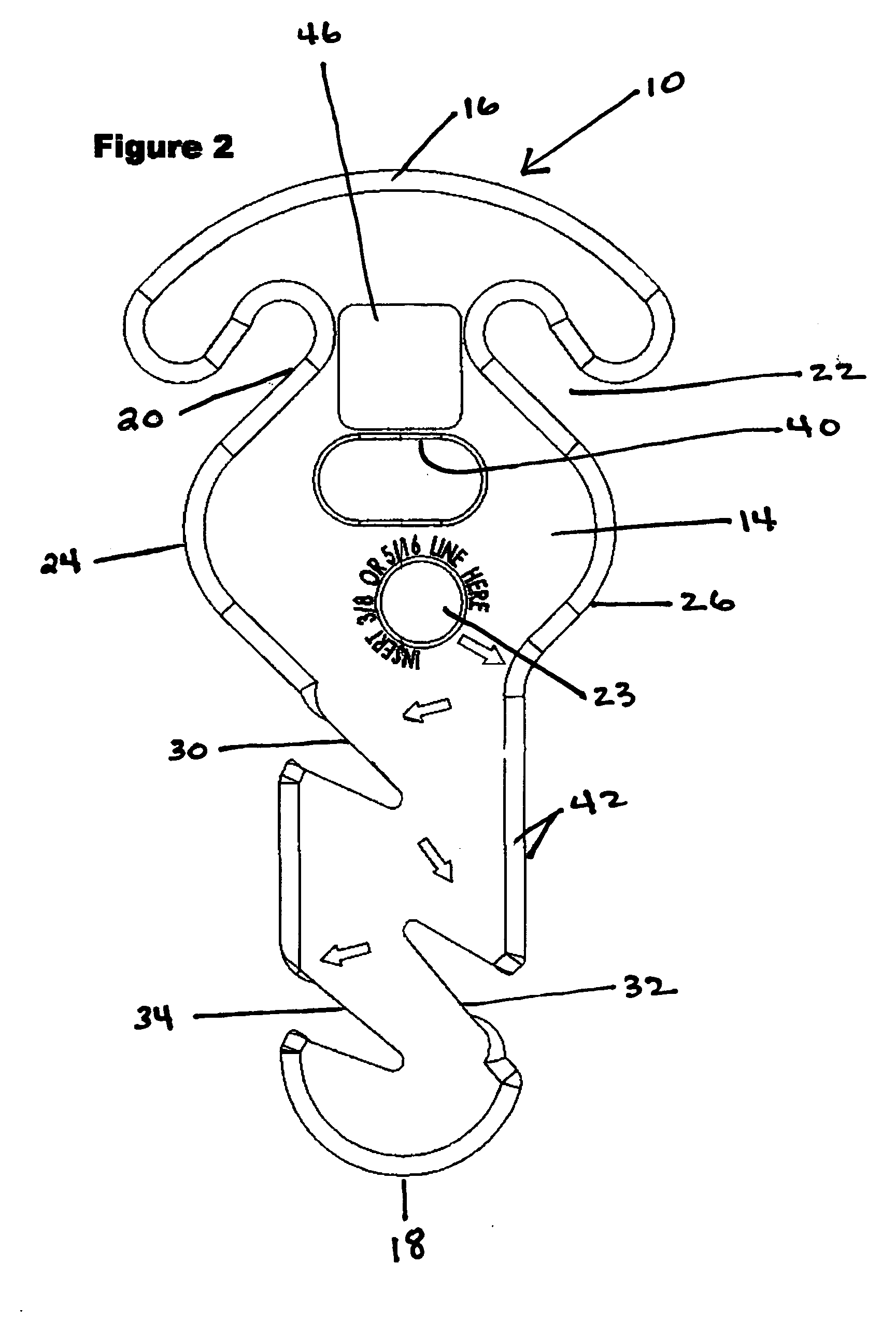
[0018] The invention can best be understood by referring to all of the Figs. where the tensioning / coupling apparatus is generally illustrated by reference numeral 10 as having a planar face portion 12 and a planar back portion 14, a curved top portion 16 and a curved bottom portion 18. The unit can be made from any material and preferably from a polypro...


PUM


Abstract

A rope or line tensioning and/or coupling apparatus for tensioning a rope or coupling two ropes that is formed from a planar member having judiciously located slots and a drilled hole that allows the rope to be inserted into the drilled hole, looped with a knot for passing the loop through a slot formed intermediate the side edges of the apparatus and opposing slots at the top for securing the loop portions and a series of slots at the bottom for helically winding the rope or line by inserting opposite disposed slots.

Description

TECHNICAL FIELD [0001] This invention relates to apparatus for tying an object with a line, rope and the like and applying tension thereto and / or coupling two lines, ropes or the like together. BACKGROUND OF THE INVENTION [0002] As one skilled in this technology readily realizes, it is often difficult to tie an object like a boat to the dock, or a bumper to a boat or tie down a load on a cargo bed and be able to apply tension when attempting to knot the rope or line together. For example, loads on the bed of a truck are tied down by placing a link chain over the load and anchoring it to the structure of the truck. A ratchet type of mechanism carries a hook that attaches to one of the links of the chain that takes up the slack of the chain by a ratcheting mechanism that is operatively connected to the hook. The operator merely pumps the handle of the ratchet so as to translate the hook until the chain is pulled taut. In the case of bumpers used to protect the hull of a boat, as anoth...

Claims


Application Information

Patent Timeline
Patent Type & Authority Applications(United States)
IPC IPC(8): B63B21/08B65H75/38F16G11/14
CPCF16G11/14B63B21/08F16G11/046
Inventor SHERMAN, KEITH E.SCHMOTZER, NORMAN H.
Owner SHERMAN KEITH E
Why Eureka
Try Eureka