Liquid crystal display device
a liquid crystal display and display device technology, applied in the direction of coupling device connection, lighting and heating apparatus, instruments, etc., can solve the problems of high brightness backlight, poor visibility of liquid crystal display devices, and large power consumption of backlights, so as to improve light utilization efficiency and reduce power consumption
- Summary
- Abstract
- Description
- Claims
- Application Information
AI Technical Summary
Benefits of technology
Problems solved by technology
Method used
Image

Examples
first embodiment
[0057] (First Embodiment)
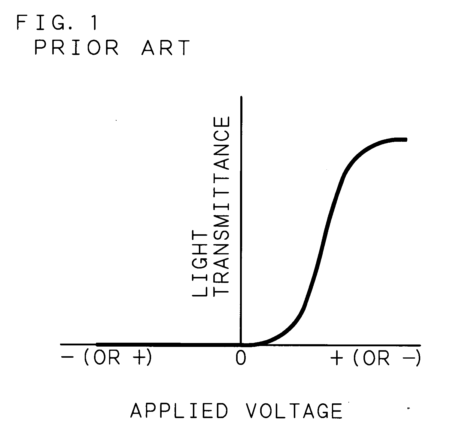
[0058] After washing a TFT substrate having pixel electrodes 40 (pixel number: 640×480, diagonal: 3.2 inches) and a glass substrate 2 having a common electrode 3, they were coated with polyimide and baked for one hour at 200° C. so as to form about 200 Å thick polyimide films as alignment films 11 and 12. Further, these alignment films 11 and 12 were rubbed with a rayon fabric, and an empty panel was produced by stacking these two substrates so that the rubbing directions are parallel and maintaining a gap therebetween by spacers 14 made of silica having an average particle size of 1.6 μm. A ferroelectric liquid crystal material composed mainly of naphthalene-based liquid crystal and having half-V-shaped electro-optic response characteristics as shown in FIG. 1 (for example, a material disclosed in A. Mochizuki, et. al.: Ferroelectrics, 133,353 (1991)) was sealed between the alignment films 11 and 12 of this empty panel so as to form a liquid crystal layer 1...
second embodiment
[0067] (Second Embodiment)
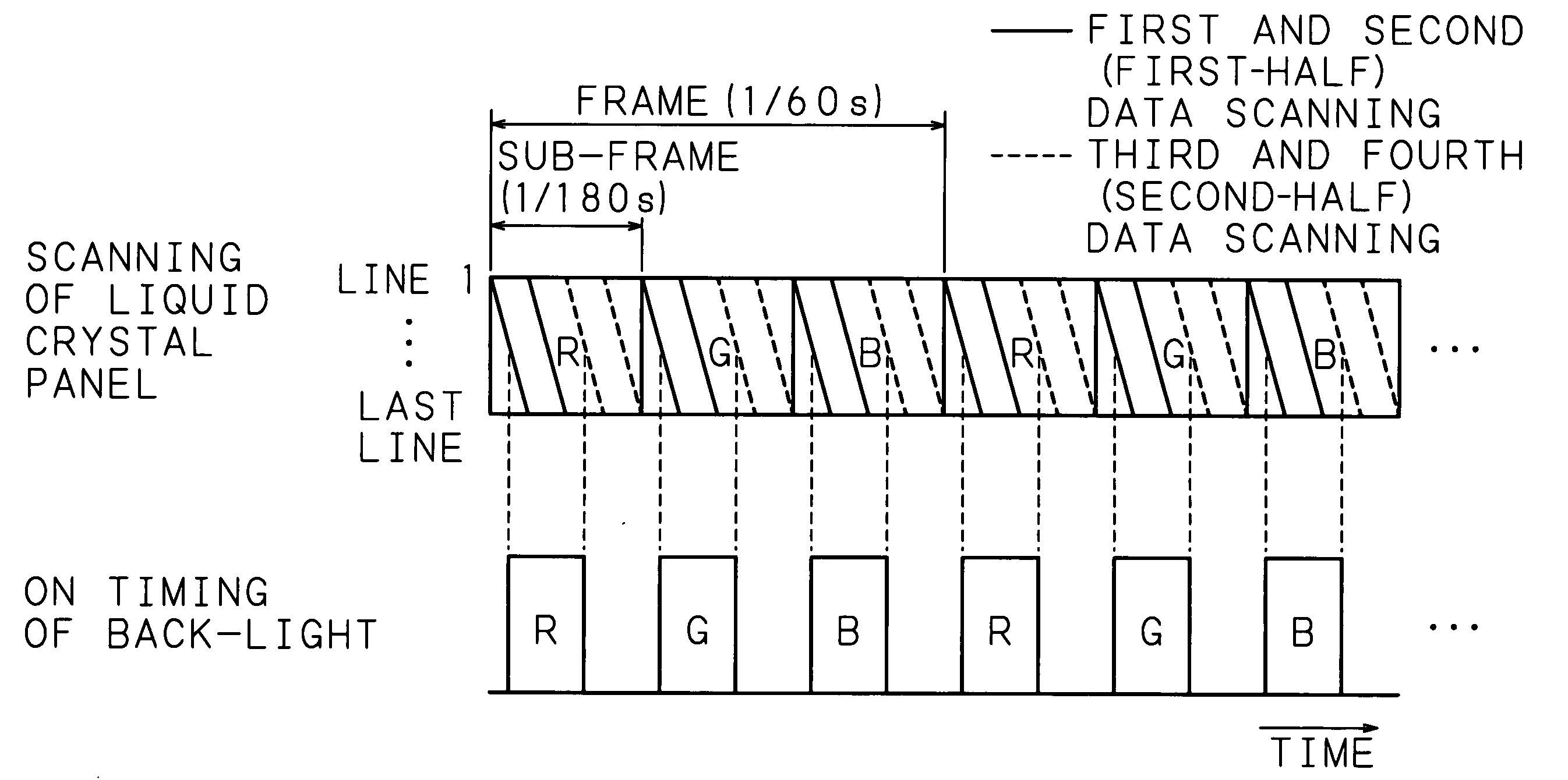
[0068] A liquid crystal panel 21 fabricated in the same manner as in the first embodiment and a back-light 22 similar to that in the first embodiment were stacked one upon another, and a color display was performed by a field sequential method, according to a drive sequence as shown in FIG. 10.
[0069] The frame frequency is set to 60 Hz, and one frame (period: {fraction (1 / 60)} s) is divided into three sub-frames (period: {fraction (1 / 180)} s). As shown in FIG. 10(a), for example, four times of writing scanning of red image data are performed in the first sub-frame, four times of writing scanning of green image data are performed in the next second sub-frame, and four times of writing scanning of blue image data are performed in the last third sub-frame within one frame. In each sub-frame, the time required for each data scanning is 25% ({fraction (1 / 720)} s) of the sub-frame ({fraction (1 / 180)} s), and the end timing of data scanning is set to coincide wit...
third embodiment
[0076] (Third Embodiment)
[0077] A liquid crystal layer 13 was produced by sealing a mono-stable ferroelectric liquid crystal material having half-V-shaped electro-optic response characteristics as shown in FIG. 1 (for example, R2301 available from Clariant (Japan) K.K.) between the alignment films 11 and 12 of an empty panel fabricated by the same process as in the first embodiment. The magnitude of spontaneous polarization of the sealed ferroelectric liquid crystal material was 6 nC / cm2. After sealing the liquid crystal material in the panel, a voltage of 10 V was applied at temperatures including the transition temperature from the cholesteric phase to the chiral smectic C phase, thereby realizing a uniform liquid crystal alignment state. The fabricated panel was sandwiched by two polarization films 1 and 5 arranged in a crossed-Nicol state so as to produce a liquid crystal panel 21, and a dark state was provided in the absence of applied voltage.
[0078] The liquid crystal panel 2...
PUM
 Abstract
Description
Claims
Application Information
 - R&D
- Intellectual Property
- Life Sciences
- Materials
- Tech Scout
- Unparalleled Data Quality
- Higher Quality Content
- 60% Fewer Hallucinations
Browse by: Latest US Patents, China's latest patents, Technical Efficacy Thesaurus, Application Domain, Technology Topic, Popular Technical Reports.
© 2025 PatSnap. All rights reserved.Legal|Privacy policy|Modern Slavery Act Transparency Statement|Sitemap|About US| Contact US: help@patsnap.com