Methods for reducing edge effects in electro-optic displays

Inactive Publication Date: 2005-03-24
E INK CORPORATION
View PDF99 Cites 258 Cited by
  • Summary
  • Abstract
  • Description
  • Claims
  • Application Information

AI Technical Summary

Benefits of technology

[0058] In another aspect, this invention provides an electro-optic display arranged to effect the high scan rate method of the present invention. This electro-optic display has a plurality of pixels, each of which is capable of displaying at least two gray levels, the pixels being divided into a plurality of groups, and at least one pixel electrode being associated with each pixel and capable of applying an electric field thereto. The display further comprises drive means for applying waveforms to the pixel electrodes, the drive means being arranged to select each of the groups of pixels in turn, wherein all the groups of pixels are selected within a period of not more than about 20 milliseconds.

Problems solved by technology

For example, when the synchronized cut-off method is applied to an active matrix display in which the rows of the display are scanned sequentially during a scan frame period, the waveforms are considered to terminate at substantially the same time provided they terminate in the same scan frame period, since the scanning method does not allow for more precise synchronization of the waveforms.

Method used


Image

  • Methods for reducing edge effects in electro-optic displays
  • Methods for reducing edge effects in electro-optic displays
  • Methods for reducing edge effects in electro-optic displays

Examples


Embodiment Construction

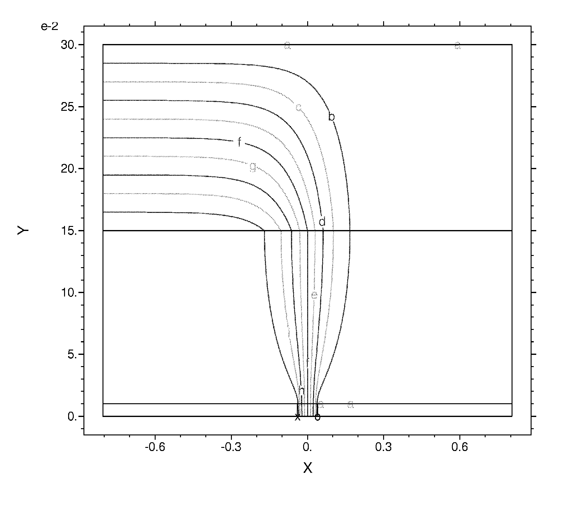
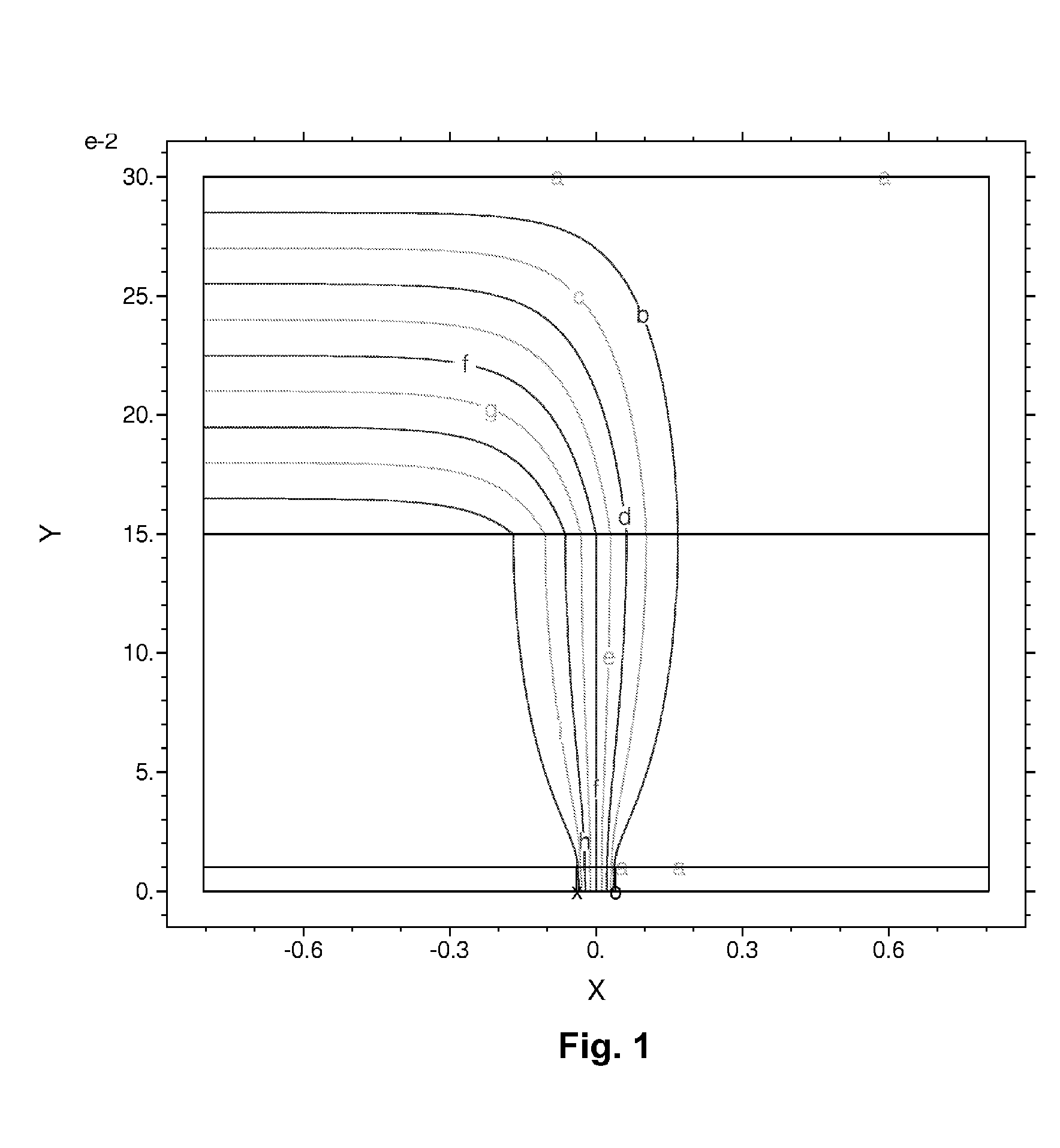
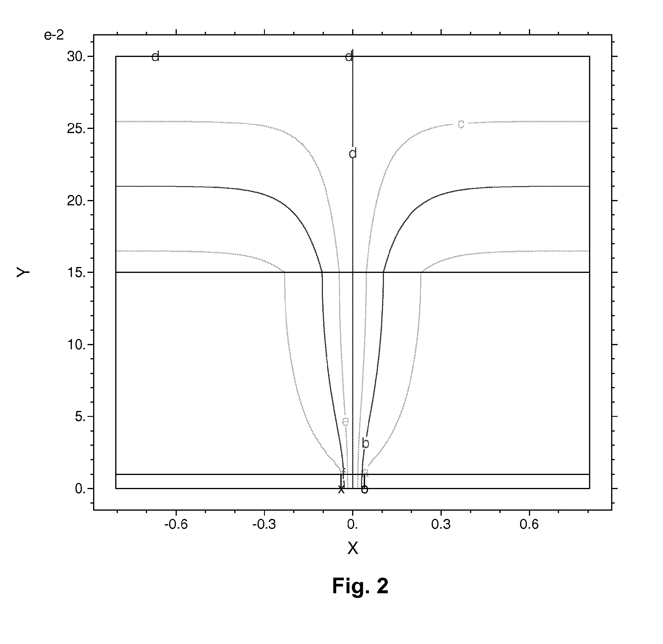
[0062] In order to understand the reasons why the methods of the present invention reduce edge effects in electro-optic displays, it is first desirable to return to FIGS. 1 and 2 of the accompanying drawings. Both these Figures show iso-potential surfaces which are generated in a model electro-optic display which has the conventional arrangement of a common front electrode, which extends across the whole display, a layer of electro-optic medium adjacent the common front electrode, a layer of lamination adhesive on the opposed side of the electro-optic medium to the front electrode, and a plurality of pixel electrodes, arranged in a regular two-dimensional array, on the opposed side of the lamination adhesive from the electro-optic medium. FIGS. 1 and 2 assume typical values for the conductivities of the lamination adhesive and the electro-optic medium, but the main features of the iso-potential surfaces are not very sensitive to the exact conductivities assumed.

[0063] It will be se...


PUM


Abstract

Edge effects in electro-optic displays are reduced by (a) ensuring that during rewriting of the display, the last period of non-zero voltage applied all pixels terminates at substantially the same time; and (b) scanning the display at a scan rate of at least 50 Hz.

Description

CROSS REFERENCE TO RELATED APPLICATIONS [0001] This application claims benefit of Provisional Application Ser. No. 60 / 481,400, filed Sep. 19, 2003. [0002] This application is also related to: [0003] (a) application Ser. No. 10 / 064,279, filed Jun. 28, 2002 (Publication No. 2003 / 0011867; now U.S. Pat. No. 6,657,772); [0004] (b) copending application Ser. No. 10 / 064,389, filed Jul. 9, 2002 (Publication No. 2003 / 0025855); [0005] (c) copending application Ser. No. 10 / 249,957, filed May 22, 2003 (Publication No. 2004 / 0027327); [0006] (d) copending application Ser. No. 10 / 879,335, filed Jun. 29, 2004, which claims benefit of the Provisional Applications Ser. No. 60 / 481,040, filed Jun. 30, 2003; 60 / 481,053, filed Jul. 2, 2003; and 60 / 481,405, filed Sep. 22, 2003 (see also International Application No. PCT / US2004 / 21000, which corresponding in substance to application Ser. No. 10 / 879,335. [0007] The aforementioned copending application Ser. No. 10 / 879,335 is also a continuation-in-part of cop...

Claims


Application Information

Patent Timeline
Patent Type & Authority Applications(United States)
IPC IPC(8): G09G3/34G09G3/36G09G3/38
CPCG09G3/344G09G3/3453G09G3/38G09G2320/0209G09G2310/061G09G2310/065G09G2310/08G09G2310/06
Inventor ZEHNER, ROBERT W.AMUNDSON, KARL R.
Owner E INK CORPORATION
Why Eureka
Try Eureka