Conveyor system

a conveyor system and conveyor belt technology, applied in the field of conveyor belts, can solve the problems of insufficient friction force between the conveyor belt and the vehicle floor, and achieve the effect of high friction material

Inactive Publication Date: 2005-03-24
AUTOMATION CONVEYORS
View PDF8 Cites 17 Cited by
  • Summary
  • Abstract
  • Description
  • Claims
  • Application Information

AI Technical Summary

Benefits of technology

[0010] Advantageously, a layer of high friction mater

Problems solved by technology

The disadvantage of this known system is that an air supply to the bags is required throughout loading and unloading operations, which means that the tractor unit of the vehicle must be connected to the trailer during loading or unloading, or a separate air supply is required.
Another d

Method used


Image

  • Conveyor system
  • Conveyor system
  • Conveyor system

Examples


Embodiment Construction

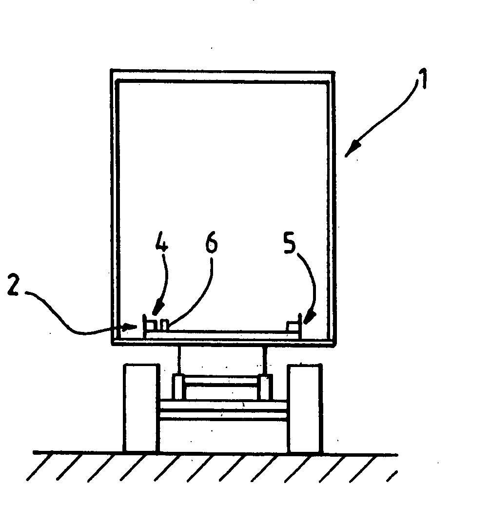
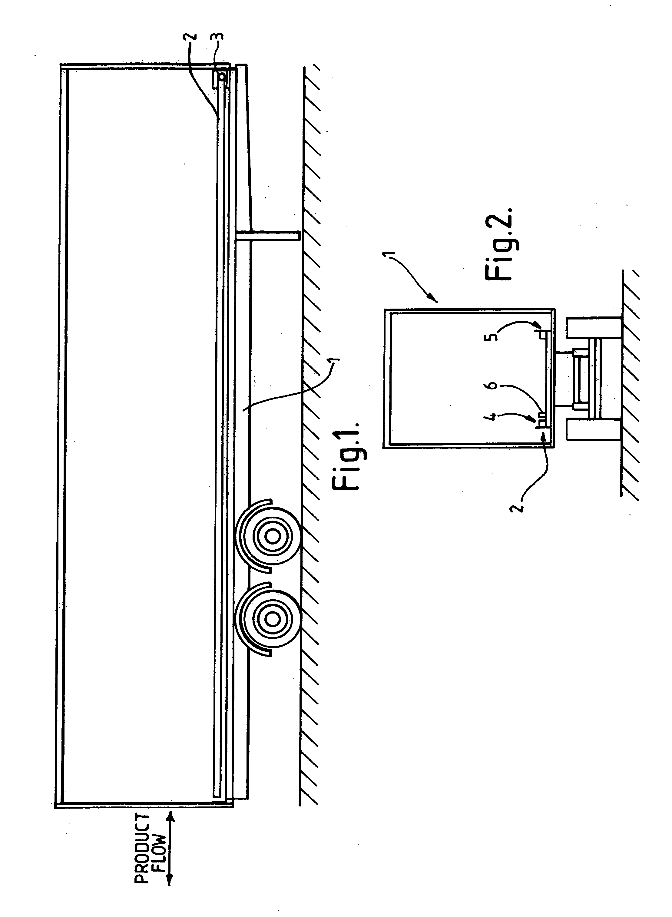
[0018] Referring to the drawings, FIGS. 1 and 2 show a trailer 1 of an articulated lorry, the trailer containing an accumulating conveyor, indicated generally by the reference numeral 2, which is mounted on the floor of the trailer.

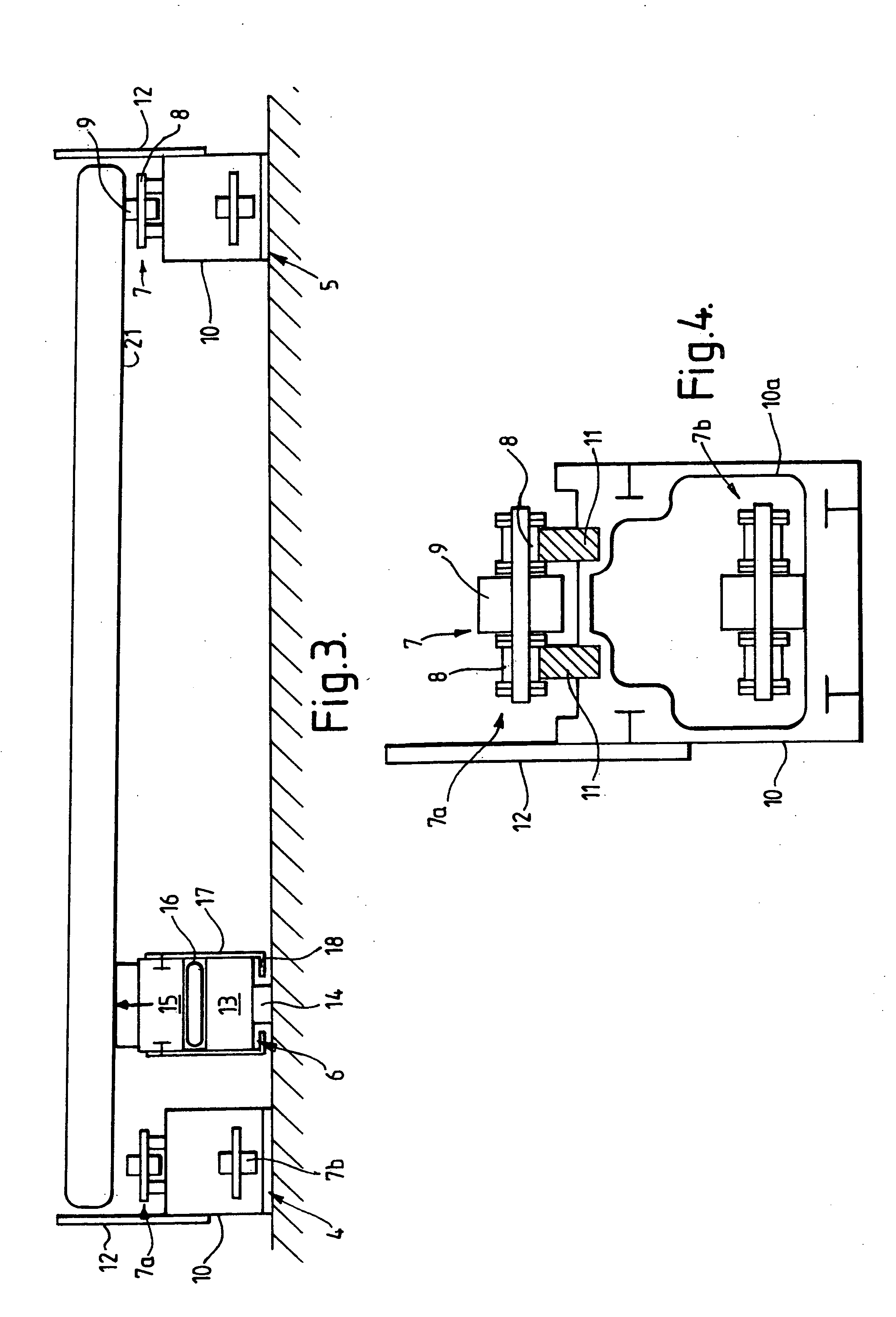
[0019] The conveyor 2 is provided with a drive drum 3 at its front end (the end adjacent to the front of the trailer 1). As shown in FIG. 3, the conveyor 2 is constituted by a pair of chain rails 4 and 5 and an airbag rail 6. Each of the chain rails 4, 5 is constituted by an endless, three-quarter inch triplex chain 7 whose links 8 each carry a roller 9, the rollers being freely rotatable with respect to their links. The working run 7a of each chain rail 4, 5 is supported above the top surface of a respective chain rail housing 10 by means of chain wear strips 11 made of polyethylene. The return run 7b of each chain rail 4, 5 is housed within a respective aluminium extrusion 10a positioned within the housing 10. The housings 10 are fixed to the floor of ...


PUM


Abstract

A conveyor system for loading pallets into and out of a vehicle comprises an accumulating conveyor and an airbag rail. The accumulating conveyor is constituted by a pair of chain rails for supporting and conveying pallets into and out of a vehicle. The airbag rail is positioned between the chain rails and adjacent to one of the chain rails. The airbag rail is constituted by a base beam, a lift beam and an airbag positioned between the two beams. The arrangement is such that, with the chain rails and the base beam fixed to the floor of a vehicle, the airbag can be inflated to raise the lift beam so as to lift an edge portion of a pallet supported by the two chain rails out of contact with said one chain rail.

Description

BACKGROUND OF THE INVENTION [0001] This invention relates to a conveyor system, and in particular to an accumulating conveyor for use inside a vehicle. [0002] In order to transport large articles such as car seats, it is known to position one or more of the articles on a pallet, and to feed the pallet into a vehicle such as the trailer of an articulated lorry using a conveyor positioned on the floor of the trailer. Typically, an accumulating conveyor is used, so that pallets can be fed into the trailer in succession so that, when a given pallet is fed into the trailer as far as it can travel, that pallet will maintain its position whilst the conveyor continues to feed further pallets into the trailer. Typically, an accumulating conveyor has one or more endless chains, the links of which carry freely-rotatable rollers. In use, a pallet is positioned on the conveyor at the rear of the trailer, and the conveyor chain drive is engaged to carry the pallet into the trailer. When that pall...

Claims


Application Information

Patent Timeline
IPC IPC(8): B60P1/36B60P1/52B65G17/00B65G47/26B65G67/20
CPCB65G17/002B65G67/20B65G47/261
Inventor WALKER, JOHN GRAEME
Owner AUTOMATION CONVEYORS
Why Eureka
Try Eureka