Brake lining for a drum brake assembly

a drum brake and drum brake technology, applied in the direction of drum brakes, brake elements, braking members, etc., can solve the problems of brake lining wear, brake linings that have to be periodically replaced, slowing the vehicle, etc., to reduce braking vibration and noise, reduce friction surface area, and reduce the effect of friction

Active Publication Date: 2014-06-03
FEDERAL MOGUL MOTORPARTS LLC
View PDF39 Cites 0 Cited by
  • Summary
  • Abstract
  • Description
  • Claims
  • Application Information

AI Technical Summary

Benefits of technology

[0006]An aspect of the present invention is to provide an improved drum brake assembly for heavy duty vehicles with reduced braking vibrations and noises. This improved drum brake assembly includes a brake lining of a high friction material, having a curved upper surface, and having a pair of oppositely facing chamfered edges. Each of the chamfered edges has an arc length of no less than one inch (1″) and is disposed at an angle of between ten and twenty-five degrees (10°-25°) from the tangent of the upper surface where it meets the chamfered edge. Despite the reduction in friction surface area between the brake lining and the drum, braking performance is not compromised because of the corresponding reduction in braking vibrations attributed to the presence of the chamfers. The reduction in braking vibrations and noises lasts until the chamfered edges are worn out, at which point, the occurrence of braking vibrations and noises will provide the driver of the vehicle with a reminder that his or her brake linings should be replaced.
[0007]According to another aspect of the invention, the chamfered edges extend along between twenty-five and thirty-five percent (25-35%) of the arc length of the brake lining. This range is advantageous for optimizing brake noise without compromising the braking performance and lining life.

Problems solved by technology

This friction converts kinetic energy from the movement of the vehicle into heat, thereby slowing the vehicle.
The friction also causes the brake linings to wear out, and therefore, the brake linings have to be periodically replaced.
Known problems with drum brakes include excessive vibrations and noise which can occur during braking.
Apart from agitating the occupants of the vehicle and the general public, such vibrations can reduce the performance of the brakes.
While effective for smaller vehicles, brake linings having steeply angled and short chamfered edges may not eliminate all noise and vibrations for heavy-duty vehicles.

Method used


Image

  • Brake lining for a drum brake assembly
  • Brake lining for a drum brake assembly
  • Brake lining for a drum brake assembly

Examples


Embodiment Construction

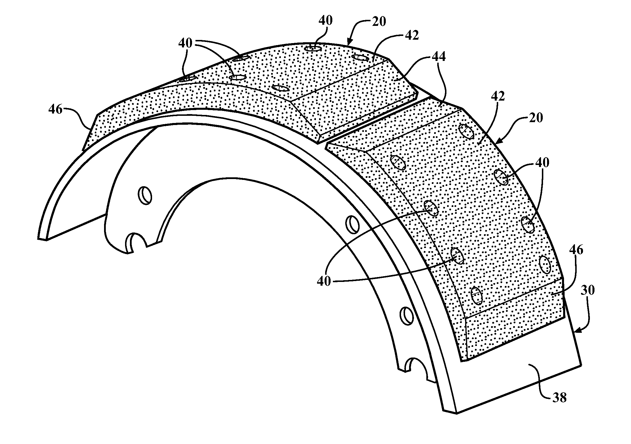
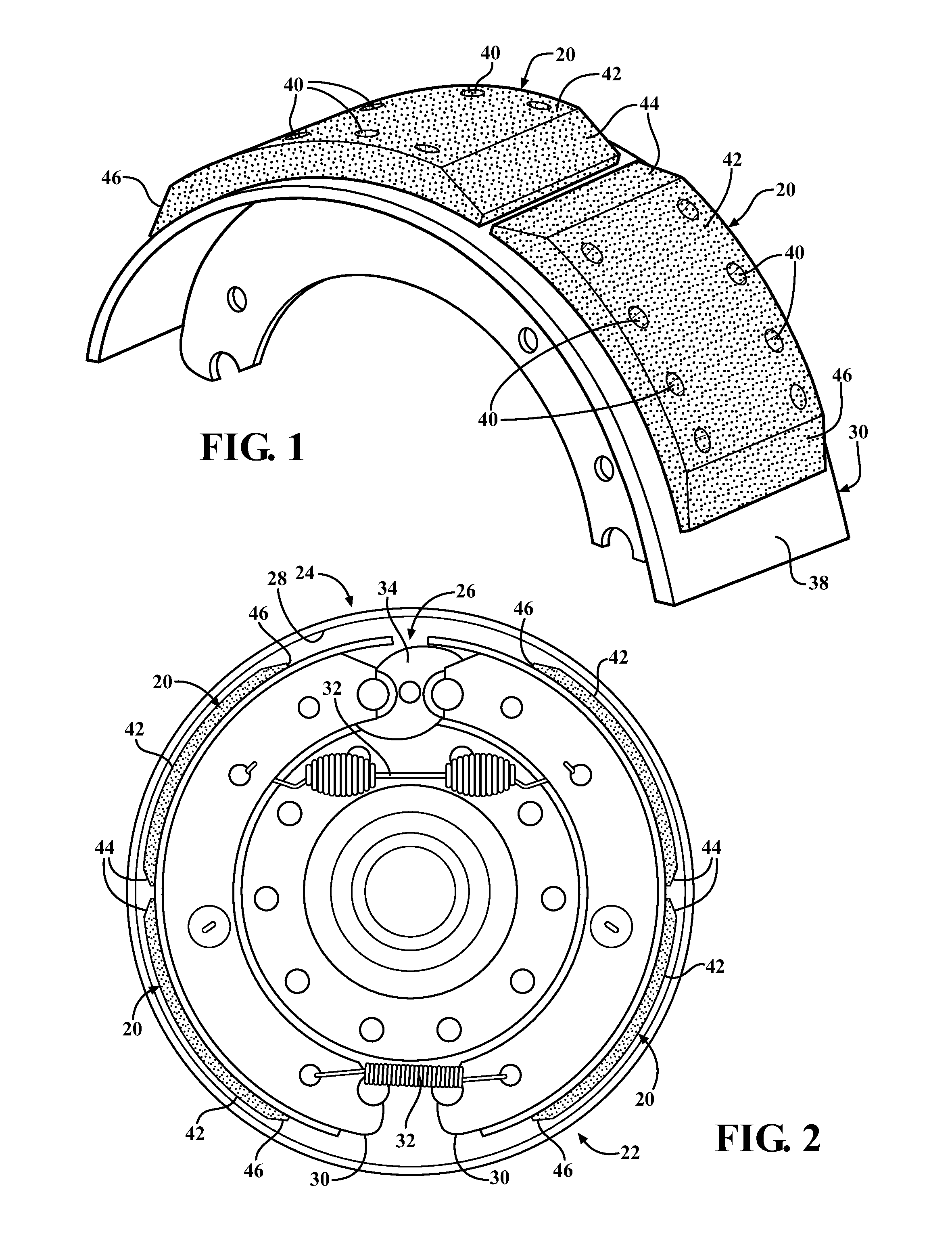
[0013]Referring to the Figures, wherein like numerals indicate corresponding parts throughout the several views, an exemplary brake lining 20 for a drum brake assembly 22 of a heavy duty vehicle is generally shown in FIG. 1. The brake lining 20 is well adapted for use in heavy-duty trucks and equipment, such as a semi-tractors and trailers, buses, dump trucks, fire trucks, garbage trucks, etc., but also finds use in other applications, such as trailers, air planes, trains, etc.

[0014]Referring now to FIG. 2, one type of a conventional type of drum brake assembly 22 for use in heavy-duty vehicles is shown. The drum brake assembly 22 includes a drum 24 and a braking mechanism 26. The drum 24 has a circular drum surface 28 projecting from a base hub and is supported for rotation on a wheel spindle (not shown) of the vehicle. The drum24 in turn mounts a wheel of the vehicle (typically via a plurality of wheel studs and nuts), and rotation of the wheel imparts rotation of the drum 24 and ...


PUM


Abstract

An improved drum brake assembly for reducing braking vibrations and noise. The improved assembly includes a pair of shoes, each extending through an arc and presenting an outer shoe surface. A pair of brake linings of a friction material are coupled to the outer shoe surface. Each of the brake linings has an upper surface and a pair of oppositely facing chamfered edges. Each chamfered edge has an arc length of no less than one inch and is disposed at an angle of between ten and twenty-five degrees from the tangent of the upper surface where it meets the chamfered edge.

Description

BACKGROUND OF THE INVENTION[0001]1. Field of the Invention[0002]The subject invention is directed to heavy-duty vehicle drum brakes.[0003]2. Related Art[0004]Despite the increasing popularity of disc brakes, drum brakes remain a popular choice for many braking applications. Conventional drum brake assemblies include a circular drum and a pair of shoes, each with at least one brake lining disposed thereon. During braking, the shoes are pushed against an inner surface of the drum, which generates friction between the brake linings and the drum. This friction converts kinetic energy from the movement of the vehicle into heat, thereby slowing the vehicle. The friction also causes the brake linings to wear out, and therefore, the brake linings have to be periodically replaced.[0005]Known problems with drum brakes include excessive vibrations and noise which can occur during braking. Apart from agitating the occupants of the vehicle and the general public, such vibrations can reduce the p...

Claims


Application Information

Patent Timeline
Patent Type & Authority Patents(United States)
IPC IPC(8): F16D65/08F16D51/20
CPCF16D51/20F16D65/08
Inventor LIU, WEIMING
Owner FEDERAL MOGUL MOTORPARTS LLC
Why Eureka
Try Eureka