Pad conditioner setup

Inactive Publication Date: 2005-03-24
BELL SEMICON LLC
View PDF4 Cites 0 Cited by
  • Summary
  • Abstract
  • Description
  • Claims
  • Application Information

AI Technical Summary

Benefits of technology

[0008] In this manner, the uniformity of the pressure applied between the conditioner and the polishing pad can be determined in a simple, quick, and inexpensive manner. Further, the method is applicable to a wide range of chemical mechanical polishers, and does not req

Problems solved by technology

If the conditioner is miss-aligned, worn out, or warped, then it might not make complete and uniform contact with the pad.
Such poor pad conditioning might result in poor processing uniformity across a substrate or from substrate to substrate, shorter pad life, increased down time, and other expenses due to yield loss.
Unfortunat

Method used


Image

  • Pad conditioner setup
  • Pad conditioner setup

Examples


Embodiment Construction

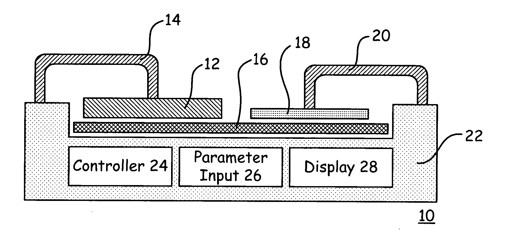
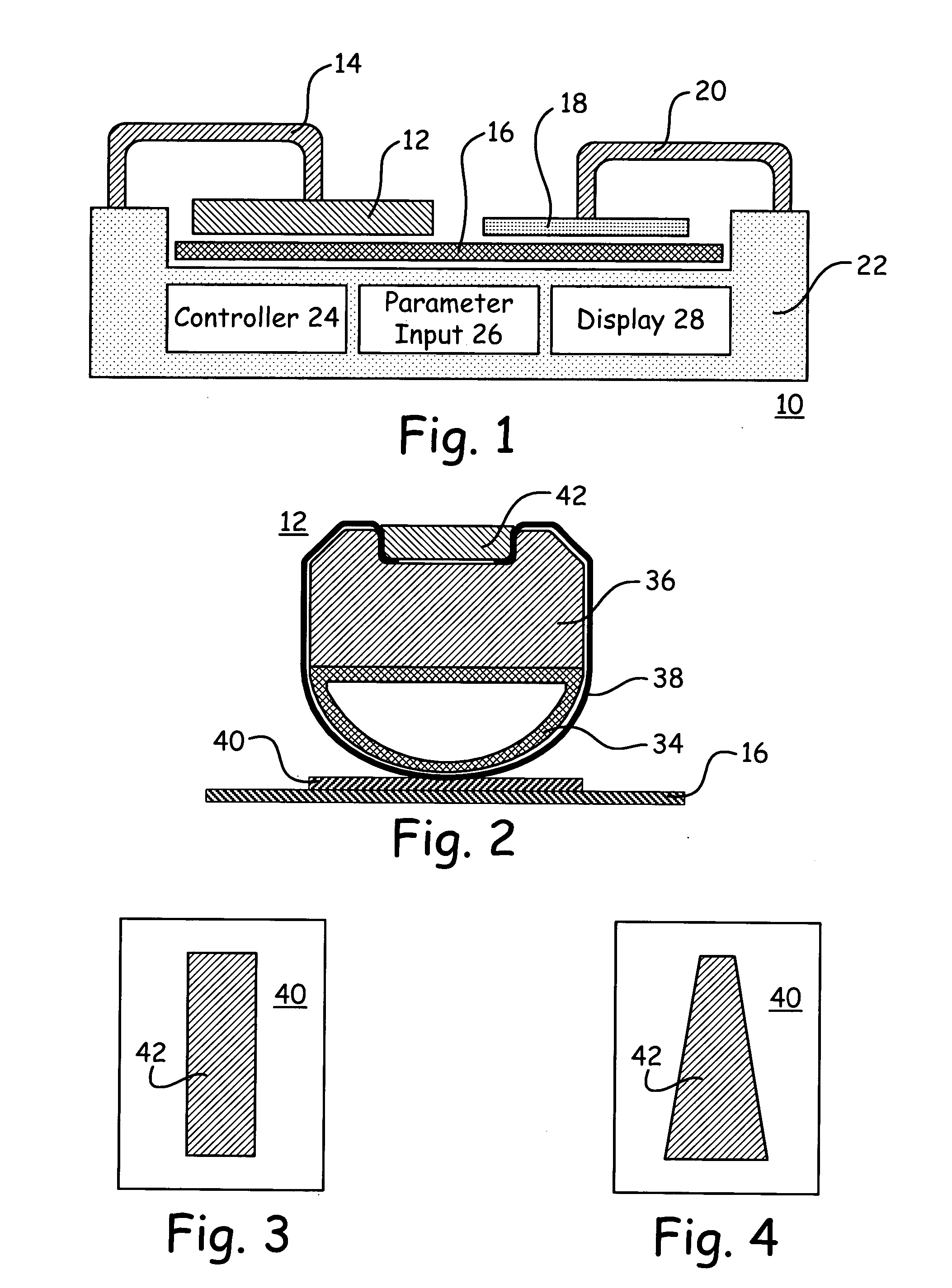
[0017] With reference now to FIG. 1, there is depicted a functional schematic of a chemical mechanical polisher 10 according to the present invention, including a conditioner 12. The conditioner 12 abrades the surface of a rotating polishing pad 16 in a controlled manner, thus conditioning the polishing pad 16. The conditioner 12 is forced against the pad 16 such as by an armature 14, which preferably sweeps the conditioner 12 across the surface of the pad 16. A substrate 18 is polished against the pad 16, under the control of an effecter 20. The polishing of the substrate 18 may be either concurrent or alternating with the use of the conditioner 12.

[0018] The conditioner 12 may be formed in any one of a number of different configurations. For example, in one embodiment the conditioner 12 is formed in the shape of a bar. In alternate embodiments, the conditioner 12 is formed in the shape of a disk. A disk-shaped conditioner 12 may be either solid like a circle or hollow like a doug...


PUM

PropertyMeasurementUnit
Timeaaaaaaaaaa
Pressureaaaaaaaaaa
Sensitivityaaaaaaaaaa

Abstract

A method for inspecting the uniformity of the pressure applied between a conditioner and a polishing pad on a chemical mechanical polisher. A sheet of pressure sensitive material is placed between the conditioner and the polishing pad, and the conditioner is lowered onto the sheet of pressure sensitive material. A desired degree of pressure is applied between the conditioner and the polishing pad, thereby creating an impression in the sheet of pressure sensitive material, and the conditioner is lifted from the sheet of pressure sensitive material. The sheet of pressure sensitive material is inspected to determine the uniformity of the pressure applied between the conditioner and the polishing pad.

Description

FIELD [0001] This invention relates to the field of integrated circuit fabrication. More particularly, this invention relates to improving the uniformity and other process characteristics of chemical mechanical polishing of integrated circuits. BACKGROUND [0002] As integrated circuits have become smaller, they have shrunk not only in the amount of surface area required, but also in the thicknesses of the various layers by which they are formed. As the thicknesses of the layers has decreased, it has become increasingly important to planarize a given layer prior to forming a subsequent overlying layer. One of the methods used for such planarization is called chemical mechanical polishing. During chemical mechanical polishing, the surface of the layer to be planarized, thinned, or both is brought into contact with the surface of a polishing pad. The pad and the substrate are rotated and translated relative to each other in the presence of a polishing fluid, which typically contains bot...

Claims


Application Information

Patent Timeline
IPC IPC(8): B24B37/04B24B49/16B24B53/007
CPCB24B53/017B24B49/16
Inventor BERMAN, MICHAEL J.FURE, JAN
Owner BELL SEMICON LLC
Why Eureka
Try Eureka