Zone controlled conveyor system and a zone controller for use therein

a conveyor system and controller technology, applied in the direction of rolling carts, instruments, computing, etc., can solve the problems of increasing the instability of the stop position, hindering the stable stop of the article at the target position, and halting the article, so as to reduce the conveying reduce the speed of the roller, and ensure the effect of attachmen

Active Publication Date: 2005-03-24
ITO DENKI KK
View PDF11 Cites 27 Cited by
  • Summary
  • Abstract
  • Description
  • Claims
  • Application Information

AI Technical Summary

Benefits of technology

[0041] The photoelectric sensor detects the presence or absence of an article without contact, thereby extremely readily attaching on the line. A further advantage of the photoelectric sensor is its high durability. The photoelectric sensor may be of a transmission type with a light-emitting member and a light-receiving member facing mutually so as to place articles therebetween or of a reflection type that receives light emitted from a light-emitting member and reflected from an article, at a light-receiving member.
[0042] The zone controller is preferably adapted to transmit a driving signal and a braking signal simultaneously to a motor for driving the driving roller so as to reduce the conveying speed of the roller.

Problems solved by technology

However, the conventional system has caused problems in relation to a halt of articles.
An unexpected inertial force resulting from the abrupt stop of the driving roller acts on the article, so that the inertial force of the article turns the driving roller that has been stopped being driven, hindering a stable stop of the article at the target position.
Further, due to the inertia force acted on an article by the abrupt stop of the driving roller, the article slips on the conveyor, increasing instability of its stop position.
Still further, as to the conventional system, due to an ununiform friction between an article and the roller, the article irregularly slips on the conveyor, hindering uniform orientations of the stopped article.

Method used


Image

  • Zone controlled conveyor system and a zone controller for use therein
  • Zone controlled conveyor system and a zone controller for use therein
  • Zone controlled conveyor system and a zone controller for use therein

Examples


Embodiment Construction

[0095] Now a preferred embodiment of the present invention will be described referring to the accompanying drawings.

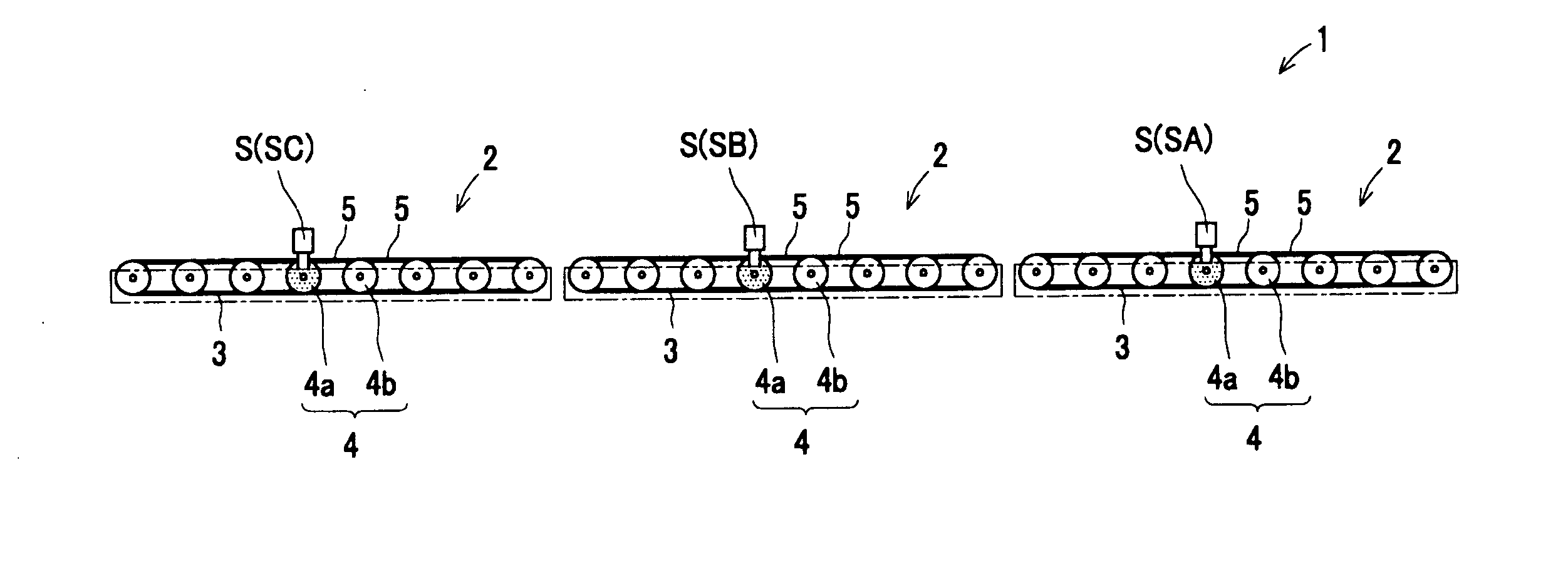
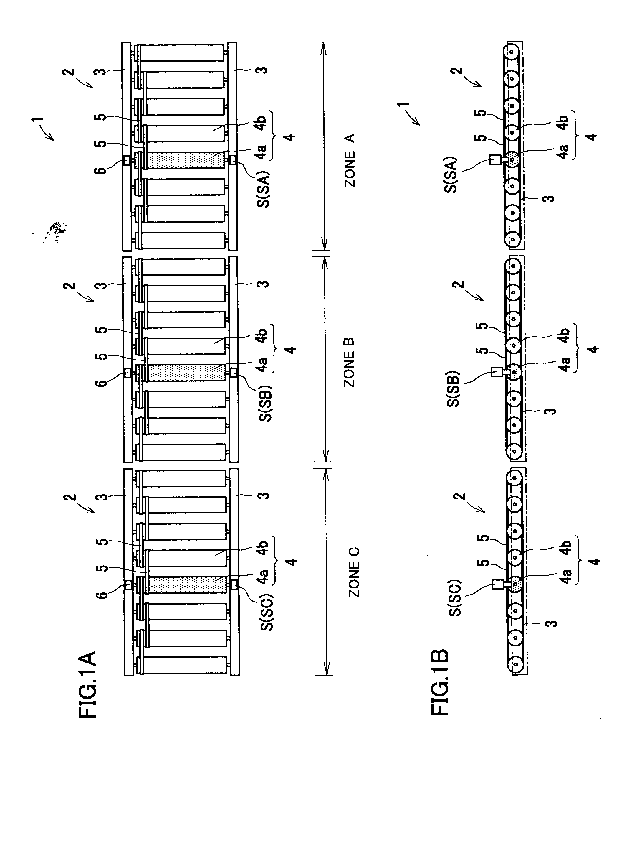
[0096] Referring to FIGS. 1A and 1B, a conveyor system (or a conveyor line) 1 is divided into a plurality of control zones including zones A, B and C, each zone having a conveyor unit 2. Each of the conveyor units 2 is made up of a plurality of conveying rollers 4, for conveying articles thereon, which are supported rotatably each through a shaft and between a pair of side frames 3, 3, positioned parallel on each side. The rollers 4 are arranged in a row in the direction of conveyance at predetermined equal intervals. The rollers 4 consist of a driving roller 4a (or motorized roller) that incorporates a driving motor for conveyance and free rollers 4b that can rotate freely. Driving belts 5 are spanned over each adjoining rollers 4 so as to transmit driving forces of the driving roller 4a to all the free rollers 4b. In this embodiment, one driving roller 4a is positio...


PUM


Abstract

The invention aims to provide a zone controlled conveyor system including a plurality of zones for control. A zone controlled conveyor system, while conveyance of any article from a zone to a downstream zone is forbidden, (a) starts operation of a driving roller in the zone at a first conveying speed slower than a prescribed standard conveying speed upon detection of a presence of an article from an immediately upstream zone of the zone, (b) operates the driving roller at a second conveying speed slower than the first conveying speed after arrival of the article at a predetermined position in the zone, and (c) halts operation of the driving roller upon detection of a presence of the article in the zone. Thereby, the system enables to stop articles at a target position accurately.

Description

BACKGROUND OF THE INVENTION [0001] 1. Field of the Invention [0002] The present invention relates to a zone controlled conveyor system, and more specifically to a system for the purpose of enabling an accurate stop of an article at a target position. Further, the present invention relates to an improvement of a zone controller for use in the zone controlled conveyor system. [0003] 2. Description of the Related Art [0004] Recently, a zone controlled conveyor system that has a conveying line consisting of a plurality of control zones (zones for control), each zone having a zone controller for controlling conveyance of articles has been developed. [0005] A patent document 1 specified below discloses such a conveyor system. [0006] The conventional conveyor system that is disclosed in the patent document 1 includes at least one driving roller and free rollers for conveyance connected by belts spanned over them in each unit. Each unit has a presence sensor for detecting the presence of an...

Claims


Application Information

Patent Timeline
Patent Type & Authority Applications(United States)
IPC IPC(8): B65G13/02B65G43/00B65G43/08B65G43/10B65G47/26
CPCB65G47/261B65G43/10
Inventor NAGAI, YOSHINORI
Owner ITO DENKI KK
Why Eureka
Try Eureka