Method for controlling the speed of a vehicle
- Summary
- Abstract
- Description
- Claims
- Application Information
AI Technical Summary
Benefits of technology
Problems solved by technology
Method used
Image
Examples
first embodiment
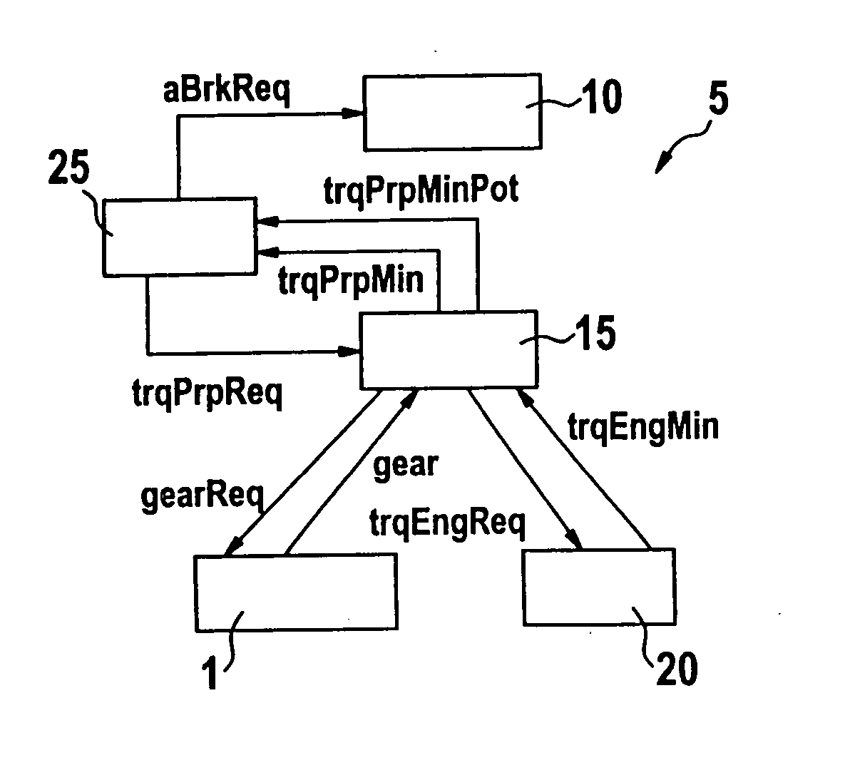
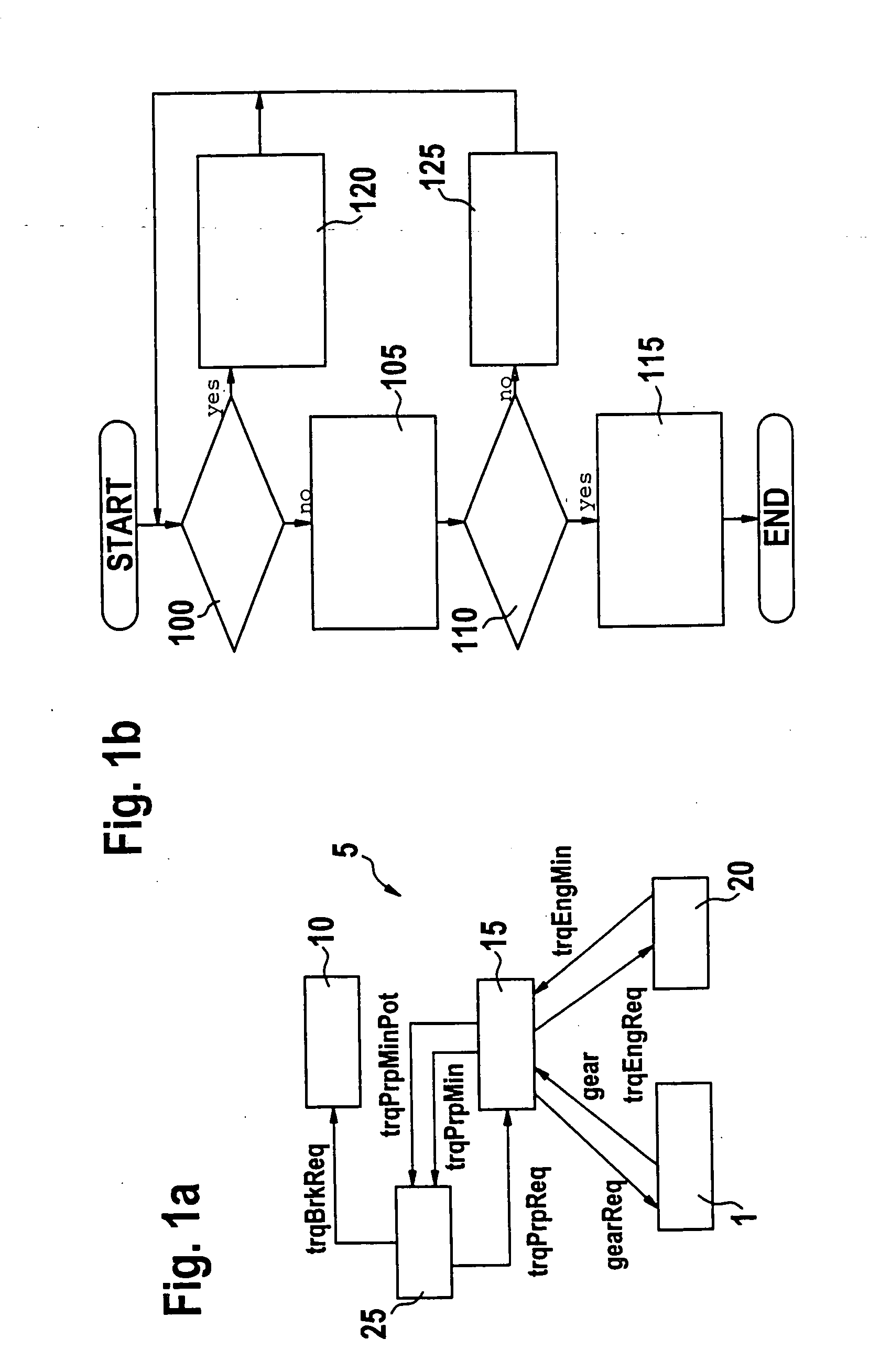
In the following, and with reference to the flowchart of FIG. 1b, the sequence of the method of the invention for FIG. 1a is described. After the start of the program, the vehicle speed controller 25 checks at program point 100 whether the desired value trqCrCtReq for the resulting drive torque, which is requested by the vehicle speed controller 25, is greater than the overrun torque trqPrpMin of the drive unit 15 in the instantaneous gear (gear). If this is the case, then the program branches to program point 120; otherwise the program branches to a program point 105.
At program point 105, the vehicle speed controller 25 detects a so-called braking case wherein the actual speed must be reduced in order to track the actual speed to the desired speed. Here, the vehicle speed controller 25 sets the desired value trqPrpReq for the drive torque equal to the overrun torque trqPrpMin in the instantaneous gear (gear) and the desired value trqBrkReq for the brake torque as follows:
trqBrkRe...
second embodiment
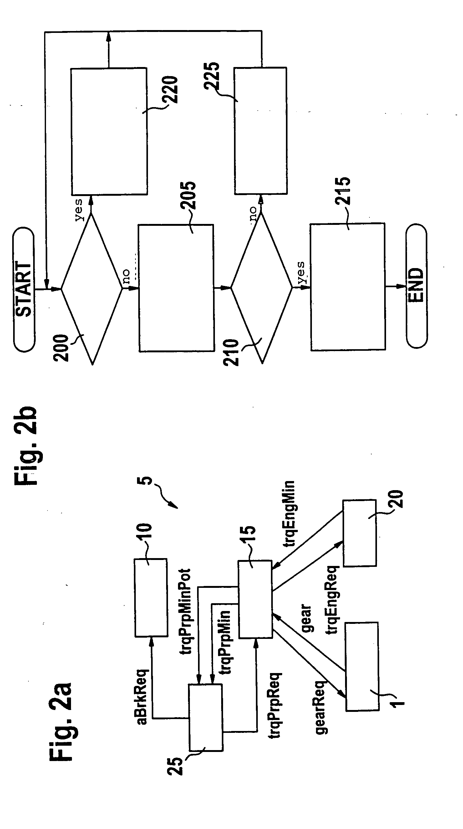
Except for the described torque interface to the brake system 10, there is also the possibility of an acceleration interface according to FIG. 2a wherein the same reference numerals identify the same elements as in FIG. 1a and, with respect to FIG. 1a, changes are only with respect to the interface between the vehicle speed controller 25 and the brake system 10. In lieu of a desired value for the brake torque, the vehicle speed controller 25 requests in an example of FIG. 2a a brake deceleration from the brake system 10. This desired value for the brake deceleration is identified as aBrkReq. In this case, the vehicle speed controller 25 has no data as to the brake torque to be developed by the brake system 10. In this way, for the embodiment of FIG. 2a, a changed flowchart according to FIG. 2b results. After the start of the program, a check is made by the vehicle speed controller 25 at program point 200 as to whether the desired value trqCrCtReq for the resulting drive torque, whic...
third embodiment
A further variation or embodiment is obtained when using a transmission control for the transmission 1 which permits no direct gear input via the drive unit 15; instead, the transmission control itself inputs the gear to be set in dependence upon a virtual accelerator pedal angle ratAccPed and further parameters which can vary depending upon the manufacturer of the transmission control apparatus. As additional parameters, the engine rpm (n) and an engine torque at full-load operation or at part-load operation can be applied in a manner known per se. Up to now, such a virtual accelerator pedal is utilized only for requesting a downshifting for a propulsion request and, in the braking case, is usually set unused to zero. According to the invention, in FIGS. 3a and 3b, it is provided to achieve a downshifting by inputting a high value for the accelerator pedal angle.
In the embodiment of FIG. 3a, the same reference numerals identify the same elements as in the first embodiment of FIG. ...
PUM
 Abstract
Description
Claims
Application Information
 - R&D
- Intellectual Property
- Life Sciences
- Materials
- Tech Scout
- Unparalleled Data Quality
- Higher Quality Content
- 60% Fewer Hallucinations
Browse by: Latest US Patents, China's latest patents, Technical Efficacy Thesaurus, Application Domain, Technology Topic, Popular Technical Reports.
© 2025 PatSnap. All rights reserved.Legal|Privacy policy|Modern Slavery Act Transparency Statement|Sitemap|About US| Contact US: help@patsnap.com


