Viterbi detection apparatus and method therefor

a detection apparatus and a technology of a detection apparatus, applied in the direction of digital signal error detection/correction, digital recording/reproduction, coding, etc., can solve the problems of erroneous viterbi operation, inability to detect 1t paths under equalizer conditions pr (a, b), etc., to facilitate high-speed operation

Inactive Publication Date: 2005-03-24
SAMSUNG ELECTRONICS CO LTD
View PDF9 Cites 12 Cited by
  • Summary
  • Abstract
  • Description
  • Claims
  • Application Information

AI Technical Summary

Benefits of technology

[0010] The present invention provides a Viterbi detection apparatus to remove paths containing 1T

Problems solved by technology

However, in the aforementioned Viterbi detection apparatuses, it is impossible to detect 1T paths under an equalizer condition PR (a, b) when hardware is impl

Method used


Image

  • Viterbi detection apparatus and method therefor
  • Viterbi detection apparatus and method therefor
  • Viterbi detection apparatus and method therefor

Examples


Embodiment Construction

[0031] Reference will now be made in detail to the embodiments of the present invention, examples of which are illustrated in the accompanying drawings, wherein like reference numerals refer to the like elements throughout. The embodiments are described below to explain the present invention by referring to the figures.

[0032] The present invention and operational advantages thereof may be fully understood by referring to the accompanying drawings and explanations thereof.

[0033] Now, exemplary embodiments of the present invention will be described with reference to the accompanying drawings to explain the present invention in detail. In the drawings, the same reference numerals indicate the same elements.

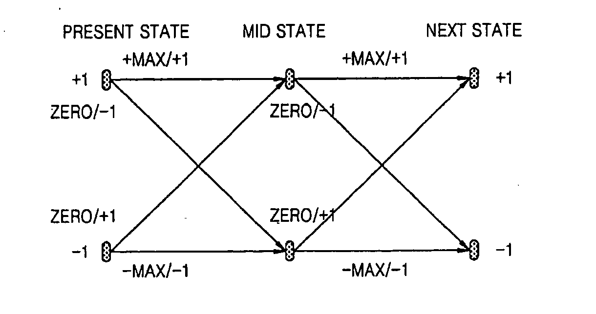
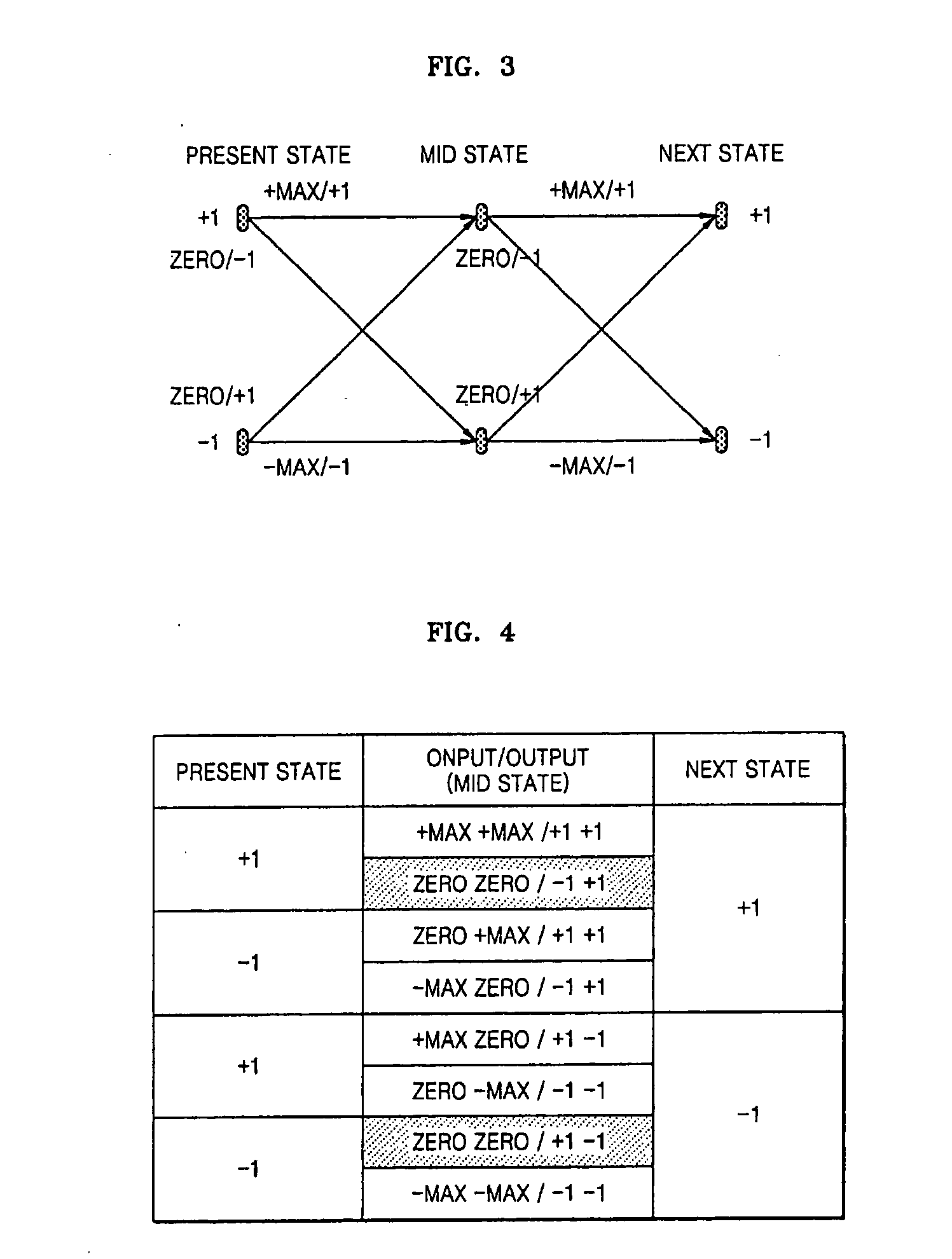
[0034]FIG. 3 is a trellis diagram of a Viterbi detection apparatus according to an embodiment of the present invention. In a radix-4 trellis diagram of FIG. 3, there is an intermediate state (MID STATE) which does not exist in a conventional radix-2 trellis diagram. An operational...


PUM


Abstract

A Viterbi detection apparatus and a method therefor remove code error paths generated in optical Viterbi detection. Accordingly, paths containing 1T code based on a code condition are removed even under a condition PR (a, b) by extending a radix structure to facilitate high speed operation.

Description

CROSS-REFERENCE TO RELATED APPLICATIONS [0001] This application claims the priority of Korean Patent Application No. 2003-65410, filed on Sep. 20, 2003, in the Korean Intellectual Property Office, the disclosure of which is incorporated herein in its entirety by reference. BACKGROUND OF THE INVENTION [0002] 1. Field of the Invention [0003] The present invention relates to a Viterbi detection apparatus and a method therefor, and more specifically, to a Viterbi detection apparatus and a method therefore, to remove a code error path occurring in an optical disk Viterbi detection apparatus. [0004] 2. Description of the Related Art [0005] In an optical disk system, binary data recorded on an optical disk are reproduced by illuminating laser beams on the disk and detecting reflected waves. In general, signals read out from the disk are RF (radio frequency) signals. The RF signal read out from the disk is not a digital but an analog signal due to physical and optical characteristics of the...

Claims


Application Information

Patent Timeline
IPC IPC(8): H03M13/03G11B20/18H03M13/41
CPCH03M13/395H03M13/3961H03M13/6343H03M13/4184H03M13/6331H03M13/41G11B20/18
Inventor PARK, HYUN-SOOLEE, JUNG-HYUNSHIM, JAE-SEONGLEE, JAE-WOOKCHO, EING-SEOBRYU, EUN-JIN
Owner SAMSUNG ELECTRONICS CO LTD
Why Eureka
Try Eureka