Receiving apparatus, method for displaying in conjunction with television program, and printing control method

a technology for receiving apparatuses and televisions, applied in the direction of television systems, selective content distribution, instruments, etc., can solve the problems of affecting the loss of a portion of the television picture in the area for displaying the browser picture, and the loss of the important part of the television pictur

Inactive Publication Date: 2005-03-24
PANASONIC CORP
View PDF3 Cites 44 Cited by
  • Summary
  • Abstract
  • Description
  • Claims
  • Application Information

AI Technical Summary

Benefits of technology

[0024] The present invention is conceived to solve the above problems, and an object of the present invention is to provide a receiving apparatus, a method for displaying in conjunction with a television program (TV program-linked display) and a printing control method involving the TV program-linked display that allow control over display of a browser picture and a television picture so that they are displayed in conjunction with each other (i.e., the television picture that is currently being viewed is continuously displayed without loss of the picture displayed on the screen even when the browser picture is started up on the current television picture) in order to display the television picture in front of the browser picture on the screen in a state where “entirety of picture display (complete picture display without losing any part of the picture)” of the television picture is maintained efficiently at least while the television program is being broadcasted.

Problems solved by technology

In addition, display of the browser picture as a window of the television picture may impair the important part of the television picture.
However, even the television receiver described in the above conventional art has the following problems.
First, since the browser picture is combined with the television picture, a part of the television picture is lost by the area for displaying the browser picture.
In the case where the television picture and the browser picture are displayed so that they do not overlap each other, an unused area exists on the screen, which is inefficient use of the screen.
In addition, against the viewer's wish to view the browser picture of information related to the television program willingly as a result of his / her interest in the program, it is not possible to display the browser picture in a full-screen mode because the prime purpose of the conventional art is to display the television picture.

Method used


Image

  • Receiving apparatus, method for displaying in conjunction with television program, and printing control method
  • Receiving apparatus, method for displaying in conjunction with television program, and printing control method
  • Receiving apparatus, method for displaying in conjunction with television program, and printing control method

Examples


first embodiment

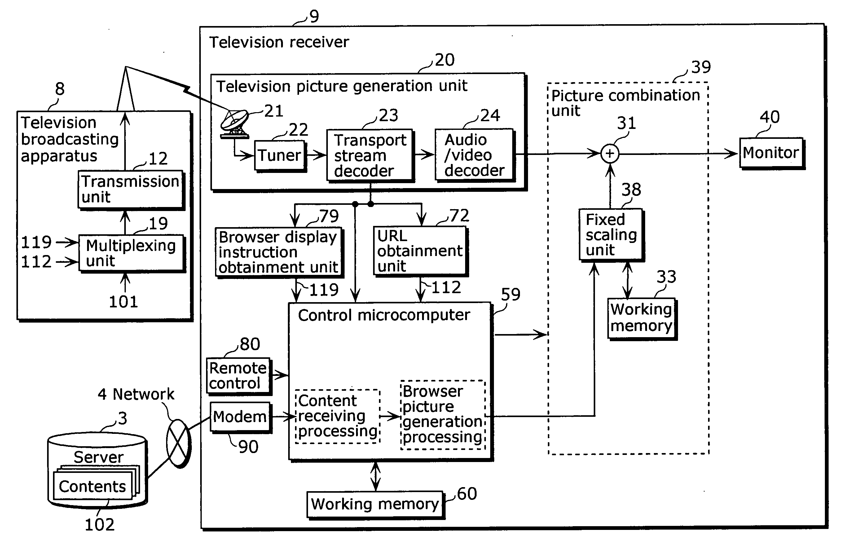
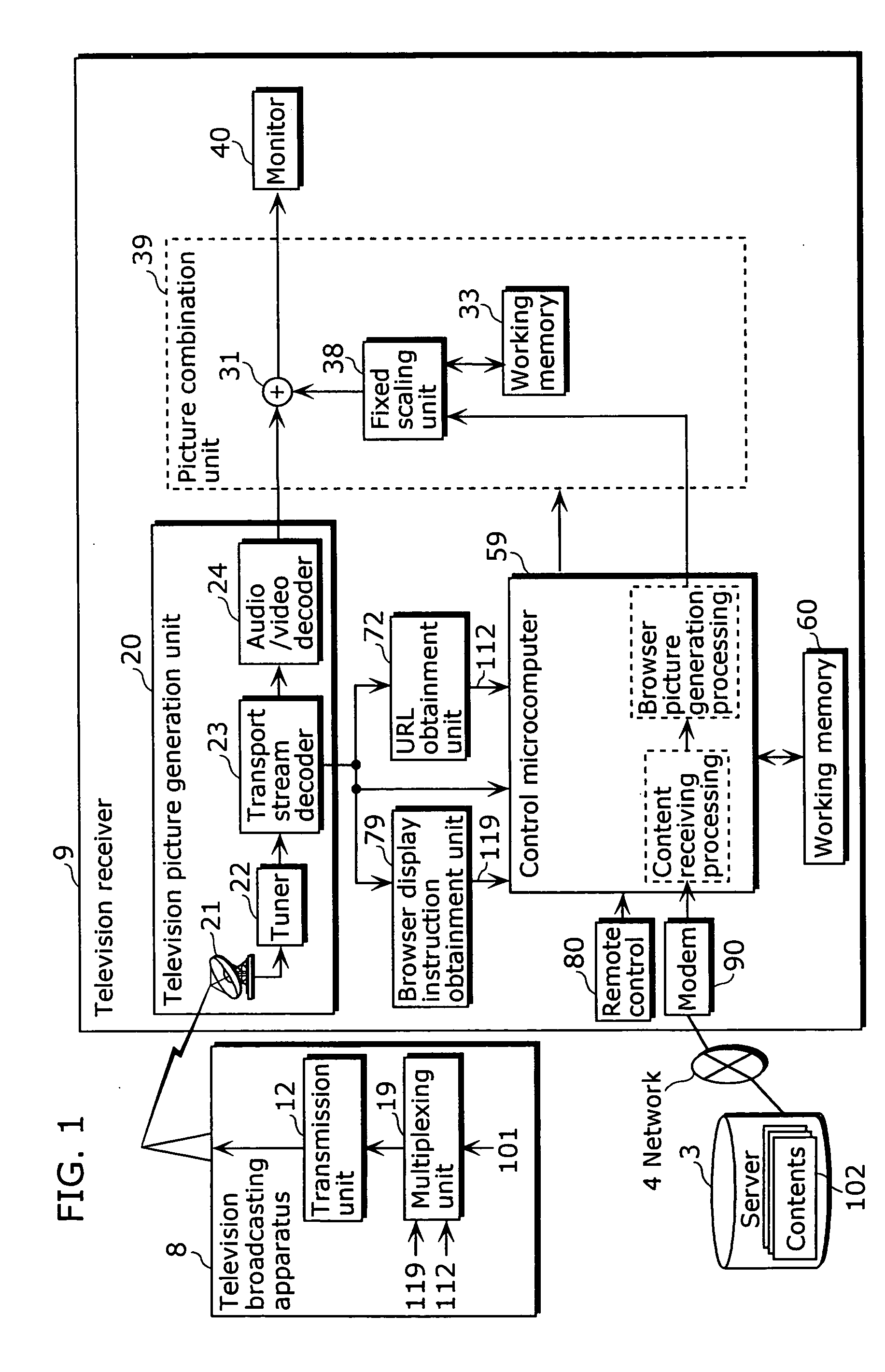
[0064]FIG. 3 is a block diagram showing a configuration of a television broadcasting apparatus and a television receiver according to the first embodiment of the present invention. In FIG. 3, a television broadcasting apparatus 1 includes a multiplexing unit 110 and a transmission unit 120. A television receiver 2 includes a television picture generation unit 200, a picture combination unit 300, a monitor 400, a microcomputer 500, a memory 600, a browser display instruction obtainment unit 710, a URL obtainment unit 720, a remote control 800 and a modem 900.

[0065] The television receiver 200 is connected to a network 4 in order to connect to the Internet. A server 3 that stores various types of contents 301 is connected to the network 4. The television receiver 2 has two functions: a function of receiving a television broadcast signal transmitted from the television broadcasting apparatus 1; and a function of displaying the contents 301 stored in the server 3 connected to the telev...

second embodiment

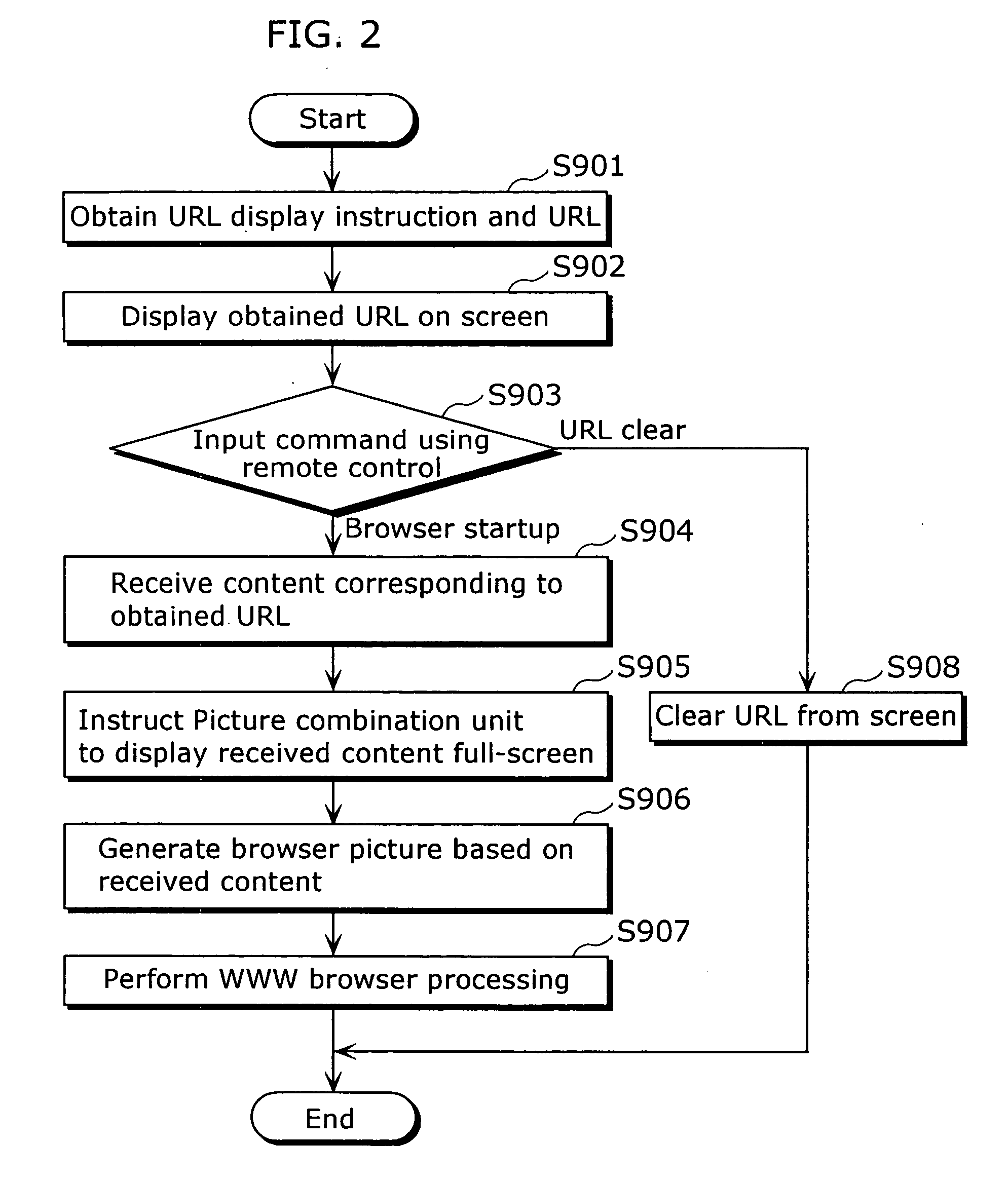
[0174] In the second embodiment, an example where whether or not to print the data to be displayed on the screen is controlled based on the combination information used for controlling whether or not to combine the browser picture and the broadcast-type picture in the first embodiment will be explained with reference to FIG. 10.

[0175]FIG. 10 is a block diagram showing a configuration of a television broadcasting apparatus and a television receiver according to the second embodiment of the present invention. Here, the same reference numbers are assigned to the same components as those in the block diagram in FIG. 3 showing the television broadcasting apparatus and the television receiver in the first embodiment, and the explanation thereof is not repeated here.

[0176] The newly added components in FIG. 10 in the second embodiment will be explained below.

[0177] Here, the newly added combination information 113 is inputted to the multiplexing unit 110 of the television broadcasting a...


PUM


Abstract

A television receiver 2 includes: a television picture generation unit 200 that receives at least one television program broadcast including a URL which indicates a server 3 where a content 301 related to the television program broadcast is stored; a picture combination unit 300 that displays the received television program on a single screen; a modem 900 that receives the content 301 from the server 3 indicated by the URL included in the television program; and a control microcomputer 500 that changes the size of the picture of the television program to a predetermined size, and controls the picture combination unit 300 so as to continue displaying the television program picture, as a window on the screen, in front of the picture of the received content 301.

Description

BACKGROUND OF THE INVENTION [0001] (1) Field of the Invention [0002] The present invention relates to a receiving apparatus having a television broadcast receiving function, a method for displaying a television broadcast program and a Web page on the Internet in conjunction with each other (hereinafter referred to as “TV program-linked display”) in the receiving apparatus having the television broadcast receiving function, and a printing control method for a picture displayed on a television screen involving the TV program-linked display. The present invention aims at an apparatus such as a stationary television system, a portable television apparatus, a set top box and a personal computer having the television broadcast receiving function built therein. [0003] (2) Description of the Related Art [0004] The recent development in digital technology and information technology (IT) has driven the further increase in capacity of communication lines and digitalization of television broadc...

Claims


Application Information

Patent Timeline
Patent Type & Authority Applications(United States)
IPC IPC(8): H04N5/445H04N7/16H04N7/24
CPCH04N5/44591H04N21/235H04N21/4316H04N21/8586H04N21/440263H04N21/4622H04N21/4782H04N21/435H04N21/47
Inventor TAKAMINE, KOUICHI
Owner PANASONIC CORP
Why Eureka
Try Eureka