Expansion joint system

a technology of expansion joints and expansion joints, applied in the direction of resiliently mounted floors, bridge structural details, bridges, etc., can solve the problems of inability the sealing of exposed thin lateral wings or flaps is not designed to withstand heavy loads or other wear and tear, and the conventional methods of holding expansion joints in place are not always satisfactory, so as to facilitate the extrusion of continuous lengths

Inactive Publication Date: 2005-03-31
E M E H
View PDF11 Cites 59 Cited by
  • Summary
  • Abstract
  • Description
  • Claims
  • Application Information

AI Technical Summary

Benefits of technology

[0009] The compression seal can be made by extruding suitable elastic material, for example, ethylene propylene terpolymers including those that are commonly known as EPDM rubber. The tubular design of the compr...

Problems solved by technology

Unfortunately, this often results in seal failure (e.g., by dislodgment) due to the loss of compression.
Exposed thin lateral wings or flaps are not designed withstand heavy loads or other wear and tear in use.
These conventional methods for holding the expansion joint seals in place are not always satisfactory.
For example, use of resins such as elastomeric concrete can be labor intensive in addition to being environmentally hazardous.
Drilling holes in precast concrete to place masonry anchor bolts for securing ...

Method used


Image

  • Expansion joint system
  • Expansion joint system
  • Expansion joint system

Examples


Embodiment Construction

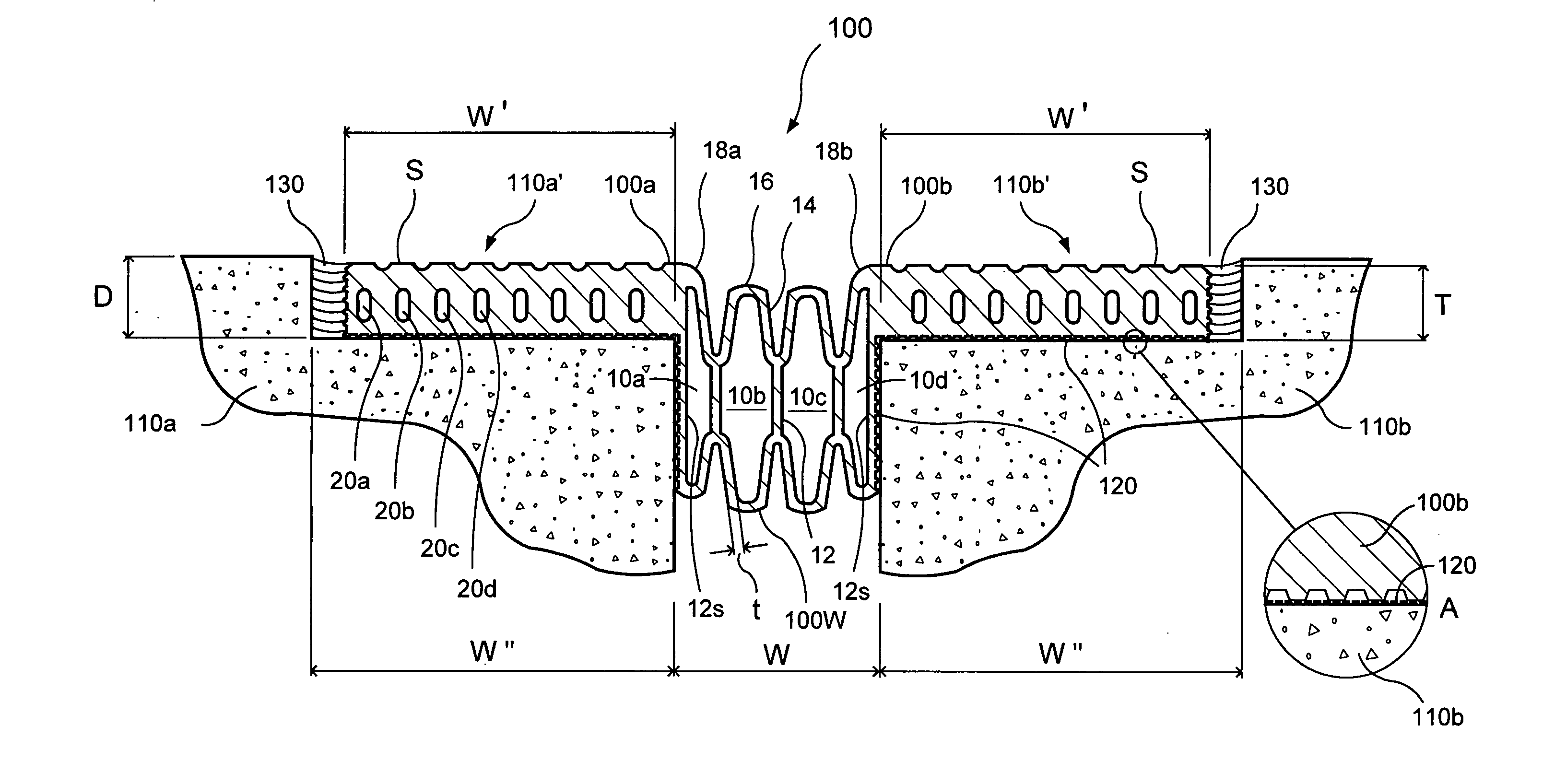
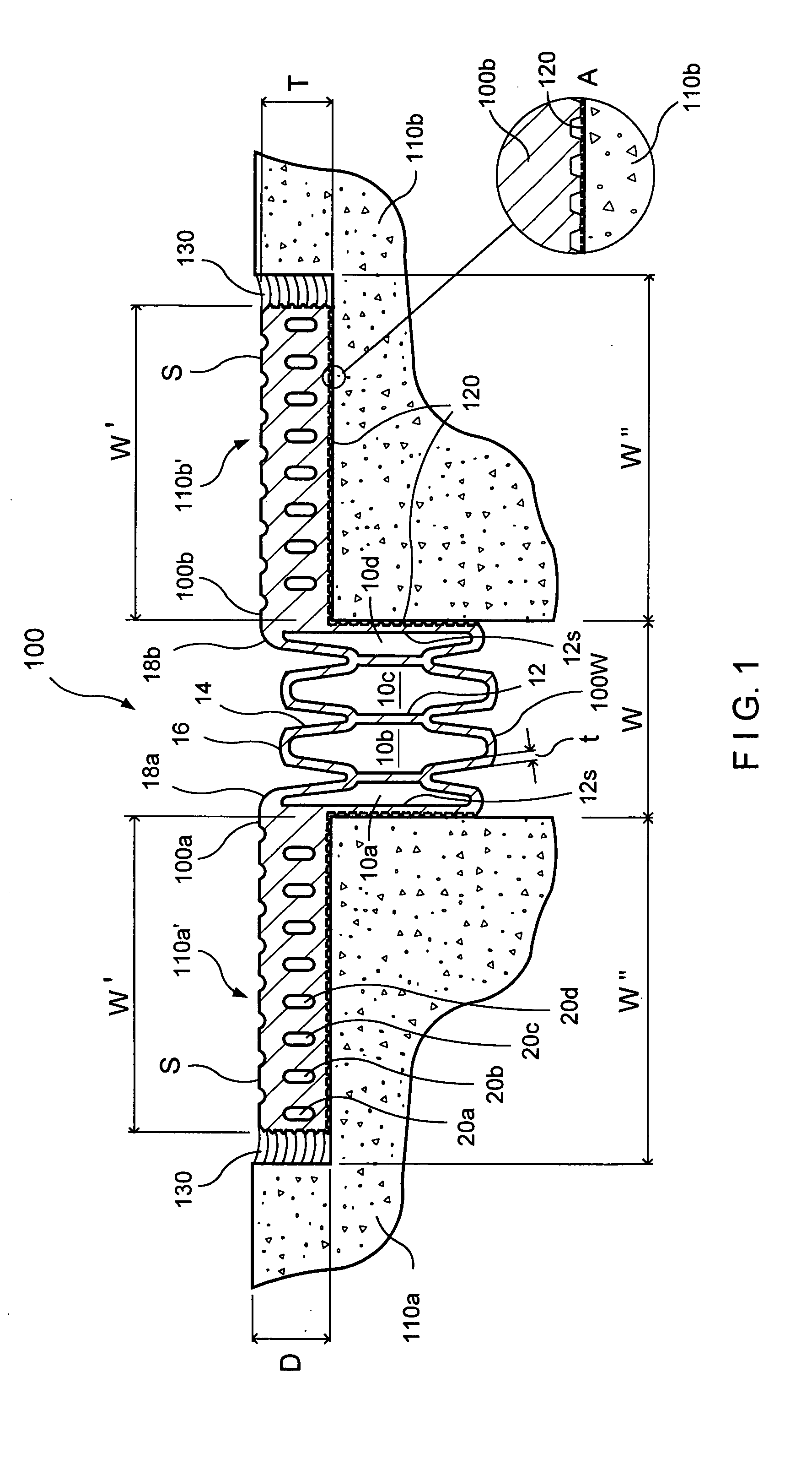
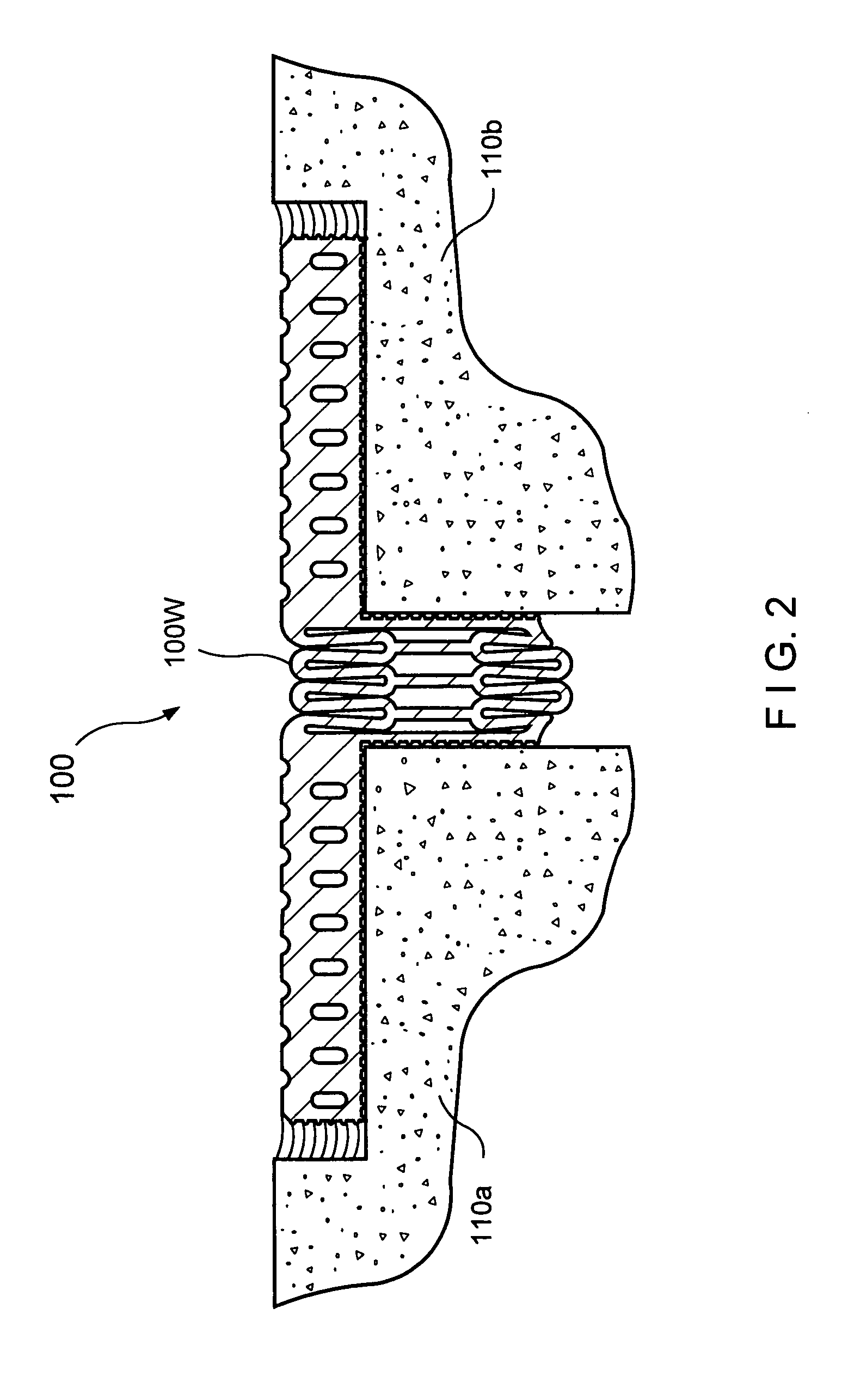
[0017] The inventive compression seals are designed for use in expansion joints between adjoining structural elements of various geometrical orientations or configurations. The expansion joints may, for example, be between coplanar concrete slabs, between stepped concrete slabs, or between a concrete slab and a wall. An exemplary compression seal 100 includes a dynamic compressible portion 100W supported between lateral load-bearing wings 100a and 100b (FIGS. 1-3).

[0018]FIGS. 1-3 show compression seal 100 installed in an expansion joint between a pair of adjoining concrete slabs 110a and 110b, which are substantially coplanar. The expansion joint has a width W between the edge walls of concrete slabs 110a and 110b. The pair of adjoining concrete slabs 110a and 110b may, for example, be precast concrete slabs of the type commonly used in concrete parking deck structures. In such use, expansion joint width W may, for example, have a nominal value of about 2 inches (FIG. 1). Longitudi...


PUM


Abstract

A compression seal for concrete expansion joints is extruded as a one-piece unit from rubber-like material. The compression seal includes a compressible sealing portion and a pair of load-bearing wings that extend laterally from the compressible sealing portion. The one-piece design facilitates easy installation of the compression seal in an expansion joint. In use, the compressible sealing portion is inserted the expansion joint. Simple zipper-like motion may be used to press fit the compressible portion into the expansion joint. The lateral load-bearing wings are bonded to concrete surfaces adjoining the expansion joint to hold the compressible sealing portion in place.

Description

FIELD OF THE INVENTION [0001] The present invention relates generally to structural expansion joints and more particularly to expansion joints between structural members such as concrete slabs and the like. BACKGROUND OF THE INVENTION [0002] Expansion joints are required in most concrete construction. Concrete undergoes physical changes in length, width, height, shape, and volume of its mass in response to changes in the temperature or the mechanical conditions surrounding it. Grooves or expansion joints are placed in a concrete structure to physically subdivide the structure into smaller structural elements. The expansion joints accommodate the compressional forces that are transmitted from abutting structural elements during movement caused by the physical changes in the concrete. Suitably designed expansion joints can preserve the structural integrity and serviceability of the concrete structure. The expansion joints may be covered or filled with flexible sealing material accordi...

Claims


Application Information

Patent Timeline
IPC IPC(8): E04B1/68
CPCE04B1/6813E01D19/06
Inventor MOULTON, PAULMINCEMOYER, BRIAN
Owner E M E H
Why Eureka
Try Eureka