
Bracket for fluid transport tube

a technology for fluid transport tubes and brackets, which is applied in the field of brackets, can solve the problems of affecting the quality of fluid transport tubes, disrupting the creation, and not fully preventing the car cabin from hearing unpleasant noises, so as to reduce the manufacturing cost, facilitate the attachment of tubes, and effectively suppress the propagation of vibrations

Inactive Publication Date: 2005-03-31
SUMITOMO RIKO CO LTD
View PDF1 Cites 175 Cited by
  • Summary
  • Abstract
  • Description
  • Claims
  • Application Information

AI Technical Summary

Benefits of technology

[0007] To ease attachment of the tube and to lower the manufacturing cost, it is preferable that the tube clamp comprises: a C-shaped (including U-shaped) clamping component made of a resin or a metal; and a vibration-absorbing layer made of an elastic material and provided inside the C-shaped clamping component. The vibration-absorbing layer may be made of a rubber, for example. However, if the C-shaped clamping component is made of a resin such as nylon (PA), the tube clamp may be made of a thermoplastic elastomer (TPE) such as an olefin (TPO) so as to mold integrally to the C-shaped clamping component.
[0008] It is desirable that C-shaped clamping component of the tube clamp has an open end portion and a non-open end portion wherein the open end portion is elongated along the fluid transport tube while the non-open end is narrowed. This configuration holds the tube firmly at the long or wide open end, thereby preventing the tube from falling off. It also allows the narrow non-open end of the tube to be continuous with the tube holding side, thereby effectively suppressing propagation of vibrations from the C-shaped clamping component to the bracket body or to the tube holding side.
[0009] The use of the bracket for a fluid transport tube of the present invention makes it possible to eliminate unpleasant noise corresponding to the propagation of vibrations of the tube to the tube holding side.

Problems solved by technology

The vibrations of the fuel tube will then propagate to the car cabin via the brackets, thereby generating vibration noise in the car cabin.
Generation of such vibration noise disrupts the creation of a comfortable environment in an automobile or other transport vehicle.
Usually, the bracket and the side of the car body have relatively high rigidity, and as a result, the use of a bracket of this type does not fully prevent the car cabin from hearing unpleasant noises derived from vibration of the fuel tube.
Additionally, the presence of the vibration-absorbing bushing between the mounting component and the bolting means does not allow vibrations to propagate from the bracket to the tube holding side through the bolting means.

Method used


Image

  • Bracket for fluid transport tube
  • Bracket for fluid transport tube
  • Bracket for fluid transport tube

Examples


Embodiment Construction

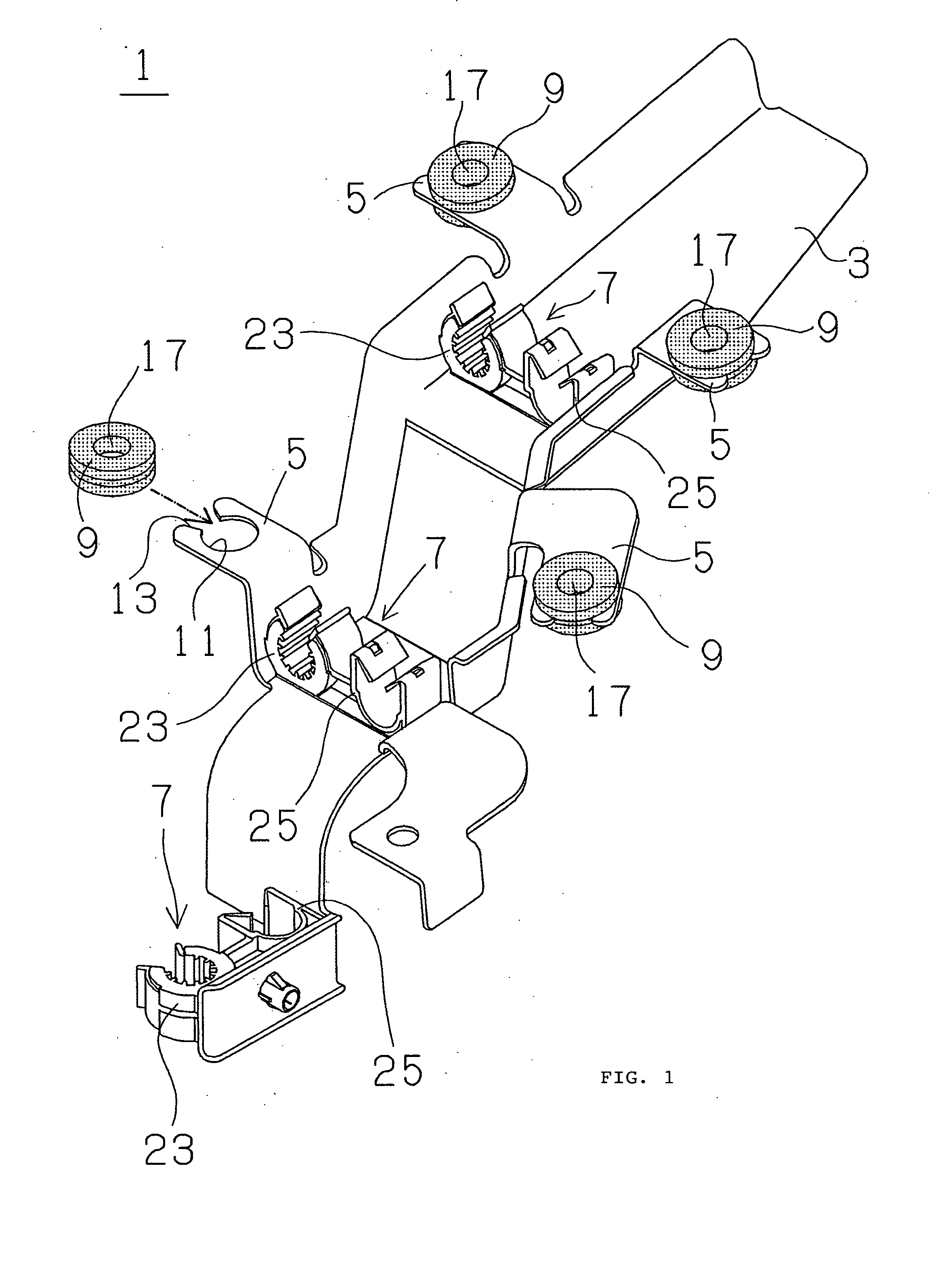
[0017] Embodiments of the present invention are hereafter described with reference to FIGS. 1-6 in the drawings.

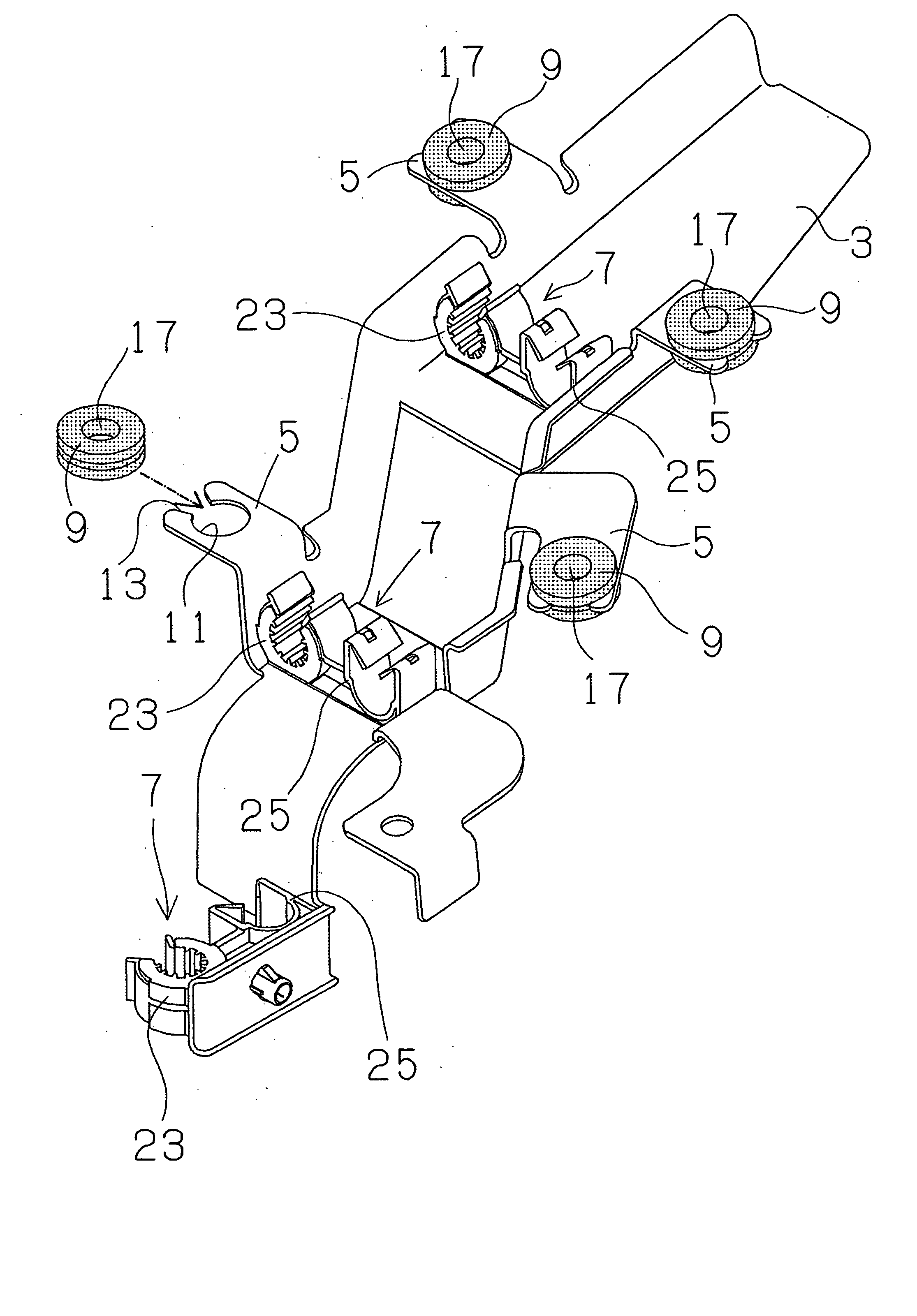
[0018] Bracket 1 representing the preferred embodiment of the present invention comprises: a bracket body 3 shaped as a relatively long plate; provided with a plurality of mounting components 5, (FIG. 1 uses four mounting components 5) which are integrally formed with the edges of bracket body 3; and provided with a plurality of clamp sets 7 (FIG. 1 uses three clamp sets 7), which are arranged longitudinally at regular intervals. The bracket body 3 is bent or curved at multiple points thereon, for example, in the longitudinal direction to trace the shape of the surface on the car body (tube holding side) where the brackets are attached.

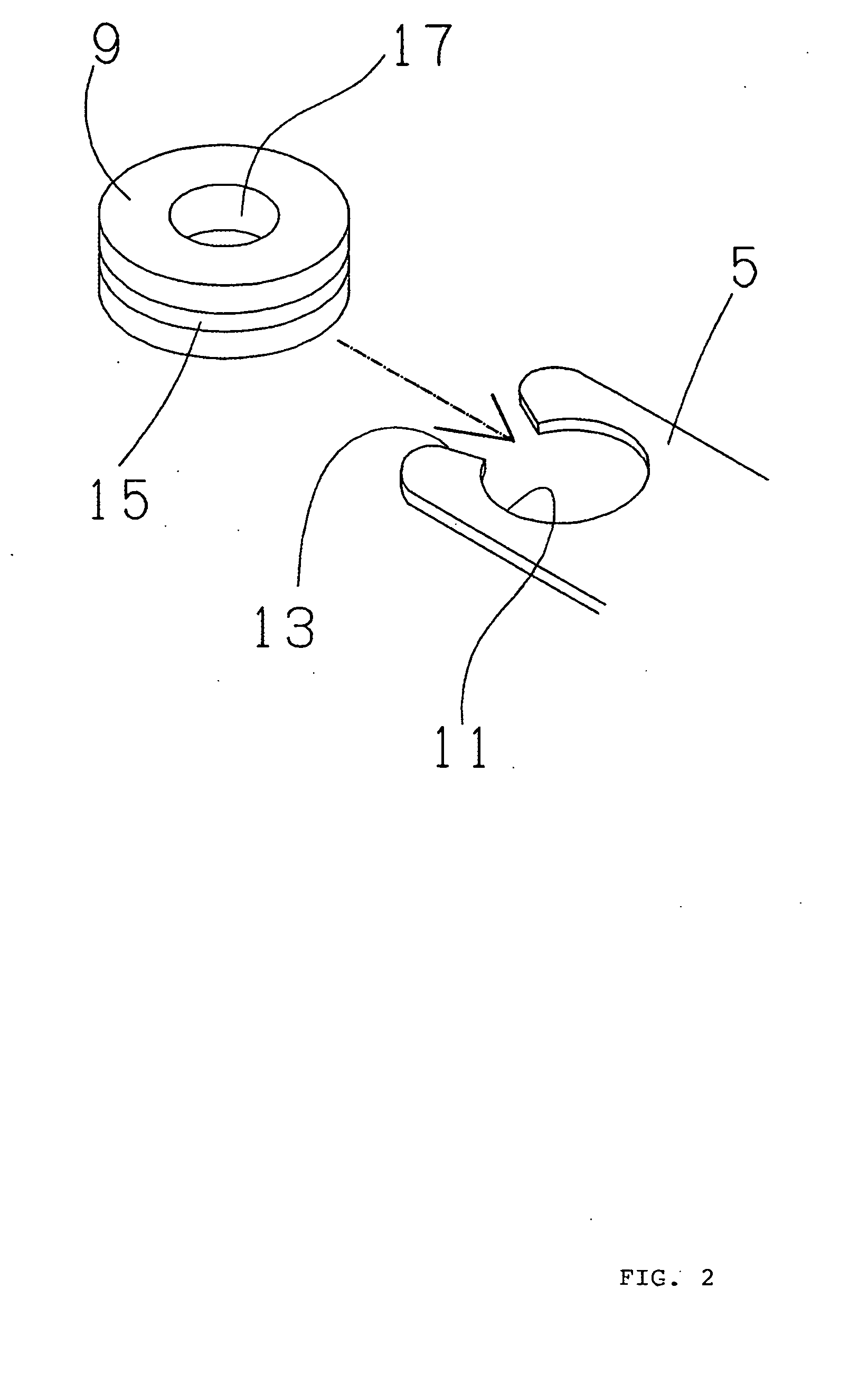
[0019] Rubber vibration-absorbing bushings 9 are fitted to each of the mounting components 5. Mounting components 5 have a circular bolt passage hole 11 and a notch-like open portion 13 at the outer end of mounting component 5. The continu...


PUM


Abstract

The present invention is a bracket for a fluid transport tube including an elongated bracket body having a length in a longitudinal direction, a tube clamp for holding the fluid transport tube in a direction transverse to the longitudinal direction, a mounting component for securing the bracket body and tube clamp to the side of a car wherein the mounting component comprises a bolt passage hole for passing a bolt having a bolt head through the passage hole to secure the mounting component to the side of the car and a vibration-absorbing bushing 9 made of a rubber-like resilient material with an annular fitting groove 15 in the middle of its outer circumference in the thickness direction thereof fitted to the mounting component 5 in such a manner to clamp part of said bushing between the bolt head and said mounting component, and another part of said bushing between said mounting component and the car body.

Description

TECHNICAL FIELD [0001] The present invention relates to a bracket that holds a fluid transport tube such as a fuel tube for transporting fuel in automobiles or other transport vehicles. BACKGROUND TECHNOLOGY [0002] To prevent a fuel tube that transports automotive fuel to an engine from contacting or interfering with other equipment, brackets must be attached at several locations on the side of the car body such that the fuel tube is supported along the side of the car body. The use of brackets to support a fuel tube along the side of the car body may permit pulsation noise from the fuel or operating noise from an engine or piston or fuel pump or the like to propagate noise to the fuel tube via the fluid or gasoline contained in the hose. The vibrations of the fuel tube will then propagate to the car cabin via the brackets, thereby generating vibration noise in the car cabin. Generation of such vibration noise disrupts the creation of a comfortable environment in an automobile or ot...

Claims


Application Information

Patent Timeline
IPC IPC(8): F16B5/02F16L3/02F16L3/16F16L3/237F16L3/26F16L55/035
CPCF16B5/0258F16L55/035F16L3/26F16L3/237
Inventor INOUE, TOMOKI
Owner SUMITOMO RIKO CO LTD
Learn More