Charging and discharging control circuit and charging type power supply device

a control circuit and power supply technology, applied in the direction of safety/protection circuits, secondary cells servicing/maintenance, electrochemical generators, etc., can solve the problems of difficult to change delay times from the outside, long test time, and fear of ignition or burst, etc., to achieve efficient use of test time

Active Publication Date: 2005-03-31
ABLIC INC
View PDF1 Cites 24 Cited by
  • Summary
  • Abstract
  • Description
  • Claims
  • Application Information

AI Technical Summary

Benefits of technology

As described above, according to the charging and discharging control circuit and the charging type power supply device in the present invention, switching between test functions is realized without adding an external control terminal, and the efficient use of a test time is realized by setting a plurality of delay time modes in a test state.

Problems solved by technology

Thus, there is a fear of ignition or burst.
However, in a charging and discharging control circuit using the internal delay circuit, the delay times are hard to change from the outside.
Because the over-charge detection delay time is generally set to about several seconds, the test takes a long time.
According to the above-mentioned technique, there is a problem in that a circuit structure is complicated and stable operation is hard to ensure.
Such measurement takes too long time in terms of mass production and becomes a serious problem in view of a test cost.

Method used


Image

  • Charging and discharging control circuit and charging type power supply device
  • Charging and discharging control circuit and charging type power supply device
  • Charging and discharging control circuit and charging type power supply device

Examples


Embodiment Construction

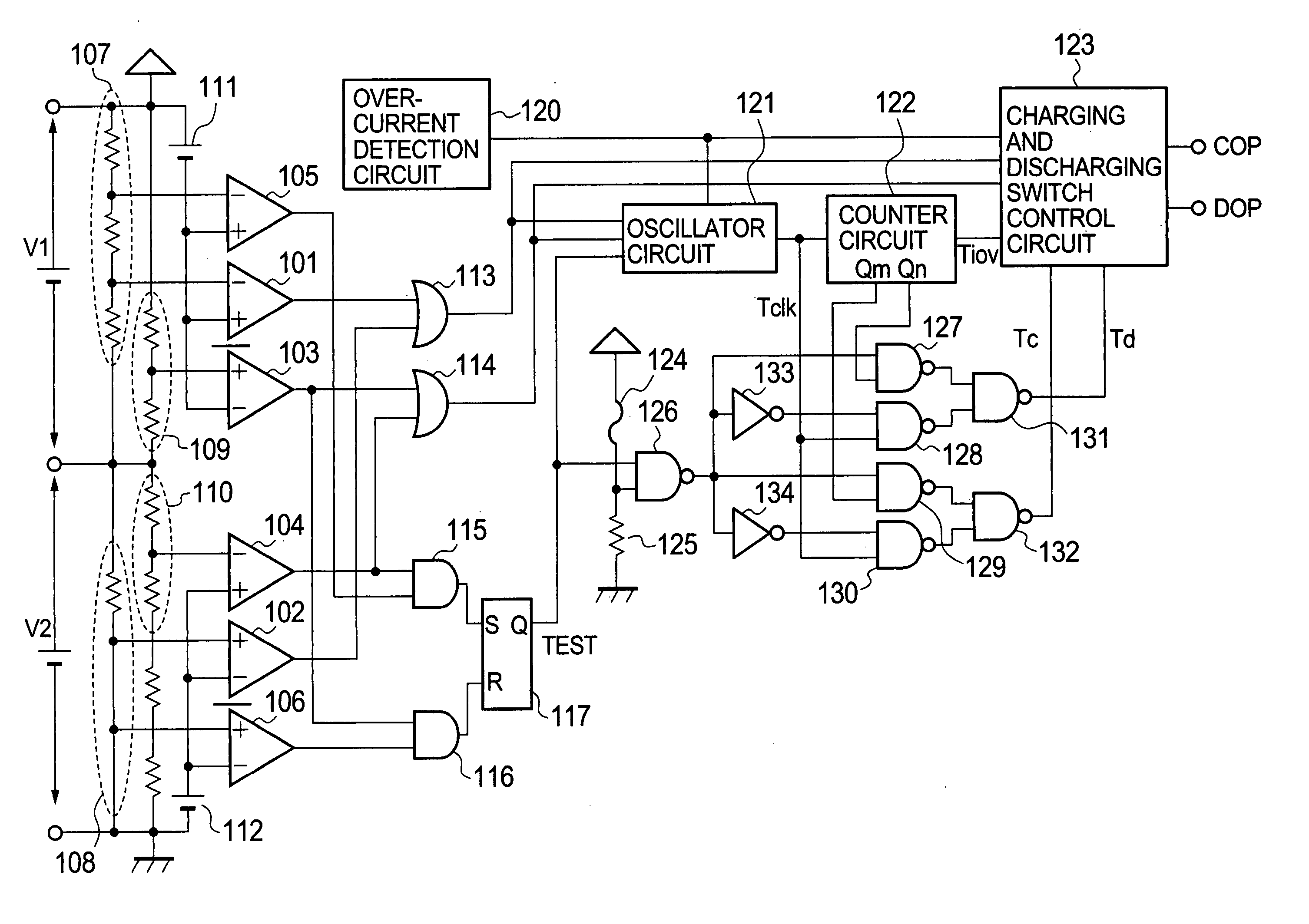
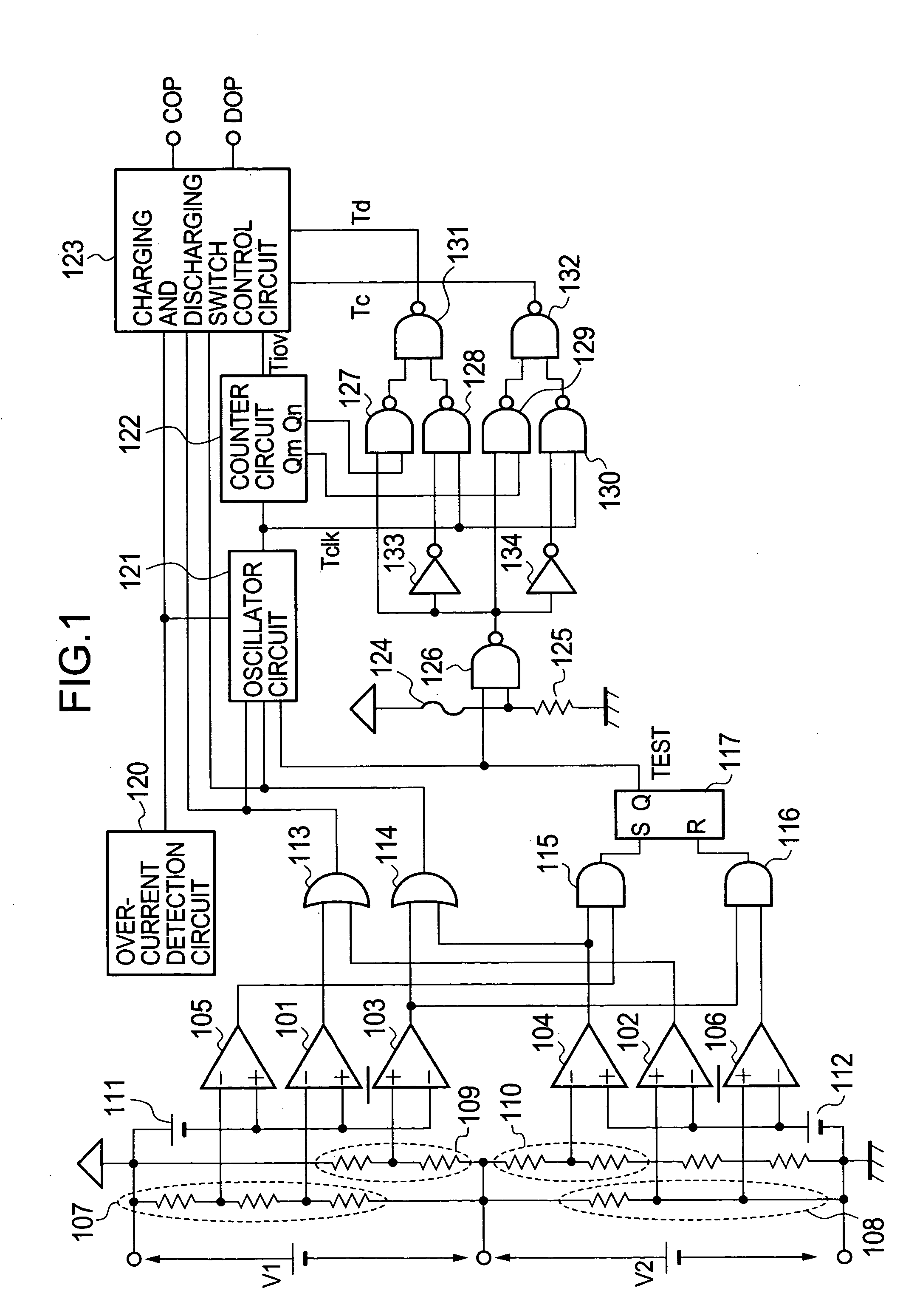
Hereinafter, an embodiment of the present invention will be described in detail with reference to the accompanying drawings. FIG. 1 is a circuit diagram for explaining a charging and discharging control circuit according to the embodiment of the present invention. In FIG. 1, the charging and discharging control circuit includes an over-charge detection comparator 101 for a battery cell-1, an over-charge detection comparator 102 for a battery cell-2, an over-discharge detection comparator 103 for the battery cell-1, an over-discharge detection comparator 104 for the battery cell-2, bleeder resistors 107 and 108 for over-charge detection, bleeder resistors 109 and 110 for over-discharge detection, a circuit 111 for generating a reference voltage for the battery cell-1, a circuit 112 for generating a reference voltage for the battery cell-2, an OR circuit 113 for over-charge detection, an OR circuit 114 for over-discharge detection, and an over-current detection circuit 120. The charg...


PUM

PropertyMeasurementUnit
delay timeaaaaaaaaaa
voltageaaaaaaaaaa
oscillating frequencyaaaaaaaaaa

Abstract

There are provided a charging and discharging control circuit and a charging type power supply device, which are capable of switching between a normal state and a test state without adding an external terminal for testing. A detection circuit for detecting a voltage higher than an over-charge detection voltage of a secondary battery is provided in the charging and discharging control circuit. A voltage higher than the over-charge detection voltage is applied to a battery connection terminal of the charging and discharging control circuit to switch between a normal application state and the test state. A fuse is further provided in the charging and discharging control circuit to switch between two delay time shortening modes for testing according to the presence or absence of the fuse.

Description

BACKGROUND OF THE INVENTION 1. Field of the Invention The present invention relates to a charging and discharging control circuit and a charging type power supply device, which are used for a secondary battery, and more particularly to a test function for evaluating a characteristic of the charging and discharging control circuit. 2. Description of the Related Art A lithium ion secondary battery that has significantly contributed to the widespread use of portable devices which are represented by a mobile telephone and a personal handy-phone system (PHS) is characterized by a small size, light weight, and a large capacity. Therefore, the long-time drive of the portable device and a reduction in weight thereof are realized. However, because the charging and discharging of the secondary battery are repeated, the secondary battery is more likely to be put in an over-charge state or an over-discharge state becomes higher. When the battery is put in the over-charge state, a battery te...

Claims


Application Information

Patent Timeline
Patent Type & Authority Applications(United States)
IPC IPC(8): H01M10/44H02J7/00
CPCH02J7/0026H02J7/0021Y02E60/10H02J7/0013H02J7/00302H02J7/0047H02J7/00304H02J7/00306H01M10/441
Inventor ZHANG, WEI
Owner ABLIC INC
Why Eureka
Try Eureka