Method and apparatus for controlling dynamic image capturing rate of an optical mouse

Inactive Publication Date: 2005-03-31
SUNPLUS TECH CO LTD
View PDF6 Cites 55 Cited by
  • Summary
  • Abstract
  • Description
  • Claims
  • Application Information

AI Technical Summary

Benefits of technology

[0006] The object of the present invention is to provide a method and apparatus for controlling dynamic image capturing rate of an optical mouse, which reduces frequency of lighting LED i

Problems solved by technology

It is known that the operating speed to a typical mouse is limited by the operating speed of human hand, typically between 2˜6 ips (inch per second).
However, bec

Method used


Image

  • Method and apparatus for controlling dynamic image capturing rate of an optical mouse
  • Method and apparatus for controlling dynamic image capturing rate of an optical mouse
  • Method and apparatus for controlling dynamic image capturing rate of an optical mouse

Examples


Example

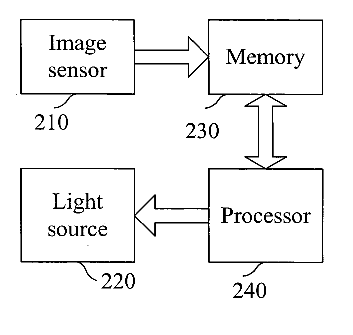
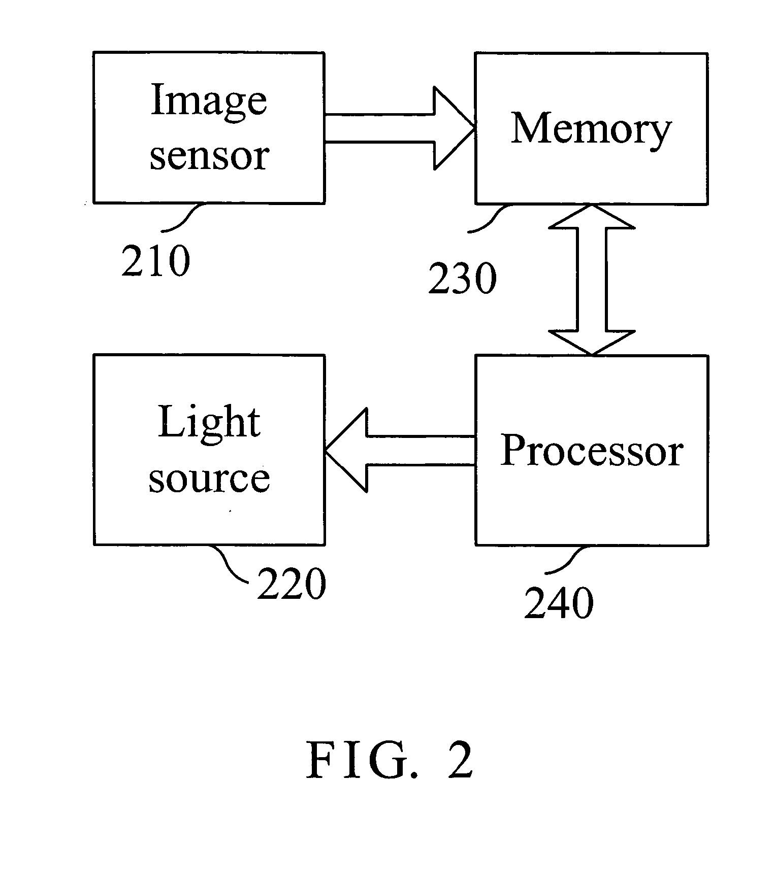
[0014]FIG. 2 is a block diagram of an apparatus for controlling dynamic image capturing rate of an optical mouse in accordance with the invention. As shown, the apparatus includes an image sensor 210, a light source 220, a memory 230 and a processor 240. The image sensor 210 is provided to capture images. Preferably, the light source 220 is a light-emitting diode (LED) that is lighted at a lighting frequency such that the image sensor can capture external images. The memory 230 stores images captured by the image sensor 210. The processor 240 is coupled between the memory 230 and the light source 220, for adjusting the lighting frequency of the light source 220 and a capturing rate of the image sensor 210 based on images captured.

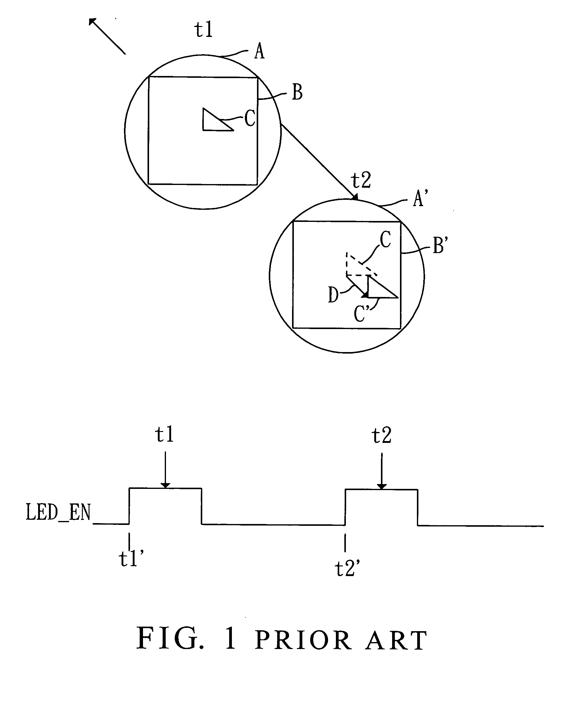
[0015]FIG. 3 is a flowchart of a method for controlling dynamic image capturing rate of an optical mouse in accordance with the invention. FIGS. 4-5 are schematic charts of operations of FIG. 3 in accordance with the invention. In FIG. 4, circle A is a cap...


PUM


Abstract

A method and apparatus for controlling dynamic image capturing rate of an optical mouse is disclosed. The optical mouse has a light source and an image sensor. The light source is lighted at a lighting frequency such that the image sensor can capture an external image. The method includes the steps: capturing a first image; capturing a second image at a next sampling time for comparing the first image and the second image and thus finding match parts to determine moving distance and speed of the optical mouse; and proportionally adjusting the lighting frequency of the light source and an image capturing rate based on the moving speed.

Description

BACKGROUND OF THE INVENTION [0001] 1. Field of the Invention [0002] The present invention relates to the technical field of optical mouse and, more particularly, to a method and apparatus for controlling dynamic image capturing rate of an optical mouse. [0003] 2. Description of Related Art [0004] A typical optical mouse applies a light-emitting diode (LED) to illuminate a mouse pad corresponding to the mouse or other object in order to obtain an image via an image sensor, and then the image sensor captures another image on the mouse pad, thus a moving vector of the optical mouse is found by comparing the two images. The moving vector is the moved distance of the mouse between two sampling points. As shown in FIG. 1, circle A is an image range captured by the image sensor when the LED illuminates on the mouse pad or other object. For image comparison, square range B is applied for consecutive captured images. For illustrative purpose, triangle C is an object in the captured image ran...

Claims


Application Information

Patent Timeline
IPC IPC(8): G06F3/03G06F3/033
CPCG06F3/0317
Inventor WANG, CHING-PINKUO, LI-FENG
Owner SUNPLUS TECH CO LTD
Why Eureka
Try Eureka