Ink supply system, recording apparatus, recording head, and liquid supply system

a technology of liquid supply system and recording head, which is applied in the direction of printing, etc., can solve the problems of inability to recover the functions of the recording head in some cases, inability to perform normal discharge operation of ink, and wasteful ink consumption, etc., to achieve compact configuration, improve recording performance and reliability of the recording apparatus and the recording head, and reduce the effect of ink consumption

Inactive Publication Date: 2005-03-31
CANON KK
View PDF13 Cites 22 Cited by
  • Summary
  • Abstract
  • Description
  • Claims
  • Application Information

AI Technical Summary

Benefits of technology

[0053] Moreover, wasteful ink consumption can be suppressed, as a large quantity of ink is not required to be sucked and exhausted from the nozzle section of the recording head for sucking and exhausting of gas from the recording head together with ink along with cleaning by transferring the gas generated in the first region at side of the recording head from the filter to the second region at side of the ink tank side by the filter disposed in the liquid chamber without using a complex mechanism or additional power. Furthermor...

Problems solved by technology

That is, when the foreign substances such as dust are mixed, there is caused a problem that, especially, the narrow discharge ports in the ink flow paths of the recording head, or sections of liquid flow paths which are directly communicated with the ports are clogged with the foreign substances.
Thereby, normal discharge operation of ink cannot be performed, and recovery of functions of the recording head can not be realized in some cases.
Thereby, ink consumption per unit time has been remarkably increased, too.
However, as, in this case, a bubble which enters into the ink supply paths easily remains in space at the upstream side of the filter members in the expanded section on the ink supply paths to cause a state in which the bubble can not be discharged, there is a possibility that smooth supply of ink is blocked.
Moreover, there is a possibility that the ink is caused not to be discharged, too, because the gas remaining in the ink supply paths becomes very small bubbles, and the bubbles are mixed into the ink which is guided to the discharge ports of the recording head.
Accordingly, there is a possibility that poor recording is caused.
However, as that the sectional areas of the ink flow paths are also increased when the areas of the filter members are made larger in order to control dynamic pressures at the filter members in the ink supply paths, the high flow speed of ink is not generated at the above-described cleaning operation even under application of the large negative pressure in the ink flow paths.
Thereby, ...

Method used


Image

  • Ink supply system, recording apparatus, recording head, and liquid supply system
  • Ink supply system, recording apparatus, recording head, and liquid supply system
  • Ink supply system, recording apparatus, recording head, and liquid supply system

Examples


first embodiment

[0067] (First Embodiment)

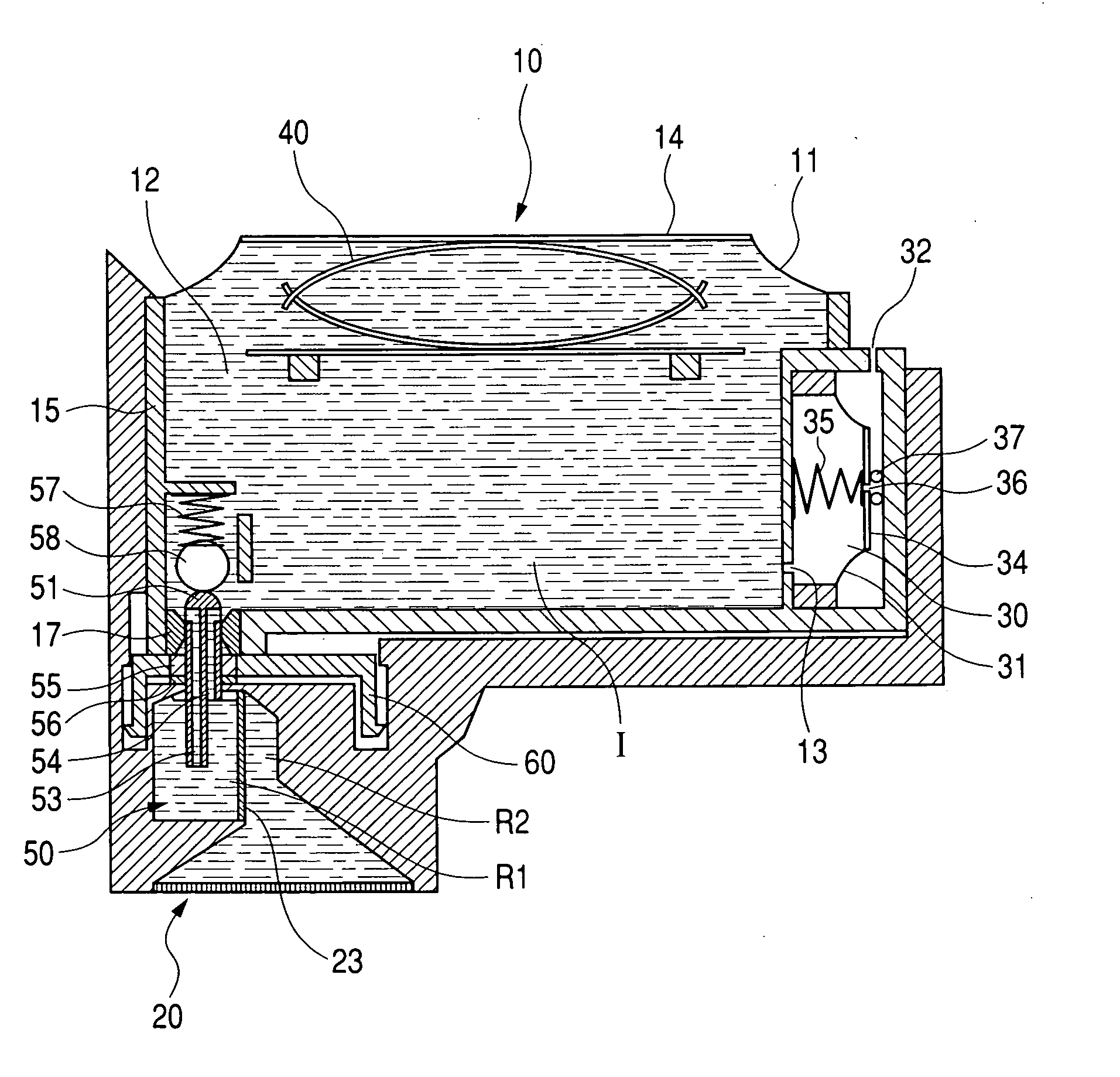
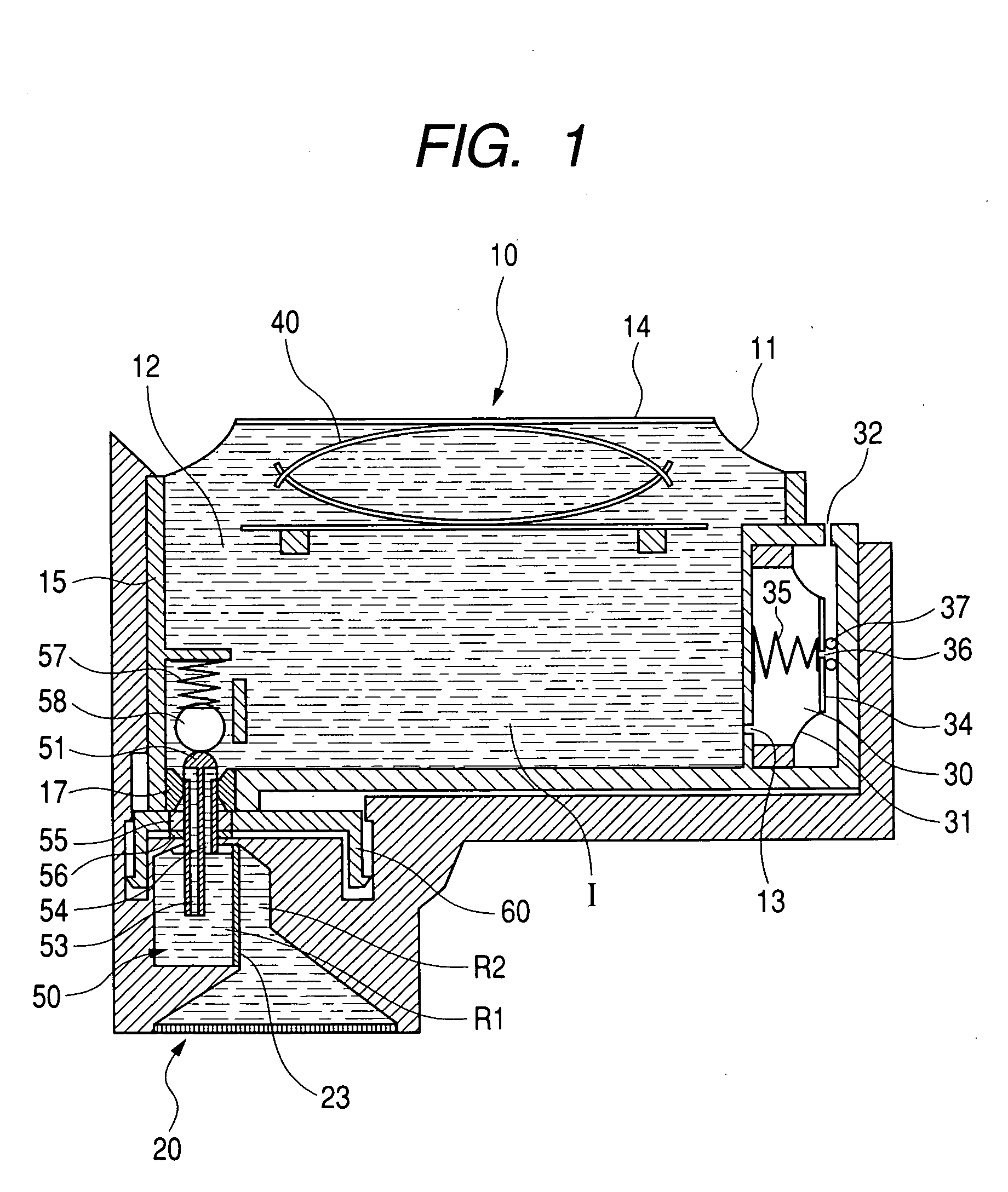
[0068]FIG. 1 is an exemplary cross section of a liquid supply system according to the first embodiment of the present invention. Generally, an ink supply system in FIG. 1 comprises: an ink tank 10 as a liquid storage container; an ink jet recording head 20 (hereinafter, called only “recording head”); and a liquid chamber 50 forming an ink supply path for connection therebetween. Although, in the present embodiment, the liquid chamber 50 and the recording head 20 are integrated into one body so that the chamber 50 and the head 20 can not be separated, the chamber 50 may be configured to be done so that the chamber 50 and the recording head 20 can be separated. Moreover, there may be a configuration in which the liquid chamber 50 is provided in a carriage equipped with the recording head 20, the ink tank 10 can be detached from the upper portion of the carriage, and an ink supply path from the ink tank 10 to the recording head 20 is formed when the ink tank 10...

second embodiment

[0110] (Second Embodiment)

[0111]FIG. 4 is an exemplary sectional view of an ink supply system which explains a second embodiment according to the present invention.

[0112] The difference between the above-described first embodiment and the present one is that the head side opening position in the air flow path 54 is equal to that of the upper inner wall surface in the liquid chamber 50, all the air remaining in the first region R1 is exhausted when the air in the first region R1 is exhausted into the ink tank 10, and there is no air remaining in the first region R1. In this case, when the quantity of the air remaining in the second region R2 exceeds a predetermined quantity, the air is moved into the first region R1, and the quantity of the air in the second region R2 is kept within the predetermined quantity. However, as the first region R1 is filled only with ink even when air movement is generated, a meniscus is quickly formed in the filter 23 and the air movement is stopped. Acc...

third embodiment

[0113] (Third Embodiment)

[0114]FIG. 5 is an exemplary sectional view of an ink supply system which explains a third embodiment according to the present invention.

[0115] In the present example, the upper portion of a filter 23 is subjected to water repelling processing, for example, by which a water repelling material is painted on the portion, and the painted portion is called a portion 23A. The contact angle with ink at the portion 23A in which the water repelling processing is performed is increased, and a meniscus pressure Pm (Refer to FIG. 3A) at the portion 23A is reduced. Therefore, the quantity of the air remaining in a second region R2 is reduced, and the air movement is started even when the difference HA between the gas-liquid interface of a first region R1 and that of the second region R2 is small. Accordingly, air can be exhausted even when the filter 23 is arranged at an angle with respect to the horizontal direction as shown in FIG. 5. As a result, the space efficienc...


PUM


Abstract

An ink supply system comprises an ink tank which contains ink, and a liquid chamber which is connected to the ink tank through a plurality of communication paths, and supplies ink taken from the ink tank to a recording head, wherein the liquid chamber, except the plurality of communication paths and a connection section to the recording head, forms a substantially sealed space; the liquid chamber is provided with a filter which can partition the inside of the liquid chamber into a first region at the side of the ink tank and a second region at the side of the recording head, and can form a meniscus of ink which is broken by a pressure of gas in the second region.

Description

BACKGROUND OF THE INVENTION [0001] 1. Field of the Invention [0002] The present invention relates to an ink supply system, a recording apparatus, a recording head, and a liquid supply system, by which, for example, a liquid such as ink is stably supplied with no wasted liquid from ink tanks and the like as a liquid storage section to a recording head, a pen, and the like as a liquid use section, and a gas in a liquid chamber between a liquid use section and a liquid storage section is exhausted into the liquid storage section. [0003] 2. Related Background Art [0004] As a liquid use apparatus, there has been, for example, an ink jet recording apparatus, which forms an image on a recording medium, by giving liquid ink to the recording medium with an ink jet recording head. Recently, such a recording apparatus has been used in many cases for recording including color recording, because the recording apparatus can make comparatively small noises at recording and form small dots with a h...

Claims


Application Information

Patent Timeline
IPC IPC(8): B41J2/175
CPCB41J2/175B41J2/17563B41J2/17556B41J2/17513
Inventor INOUE, RYOJIOGURA, HIDEKI
Owner CANON KK
Why Eureka
Try Eureka