Eureka AIR delivers breakthrough ideas for toughest innovation challenges, trusted by R&D personnel around the world.

All in one capture station for creating identification documents

a capture station and identification document technology, applied in the field of capture stations, can solve the problems of more cost and inconvenience, and more complicated transportation and configuration in an office setting, and achieve the effects of less cost and inconvenience, increased cost and inconvenience, and increased cost and inconvenien

Inactive Publication Date: 2005-03-31
DIGIMARC CORP
View PDF6 Cites 23 Cited by
  • Summary
  • Abstract
  • Description
  • Claims
  • Application Information

AI Technical Summary

Benefits of technology

[0002] In typical systems for capturing photos for identification documents, the camera assembly and workstation used to control it are separate devices. This type of capture configuration is more difficult to transport and configure in an office setting and is more costly because it involves two physically separate machines. It also presents challenges in sharing the capture station among more than one station operator, adding cost and inconvenience.

Problems solved by technology

This type of capture configuration is more difficult to transport and configure in an office setting and is more costly because it involves two physically separate machines.
It also presents challenges in sharing the capture station among more than one station operator, adding cost and inconvenience.
However, this configuration presents more costs and challenges because all capture control commands and associated data flow from a source workstation to a destination workstation connected to the camera assembly, and the destination workstation may not always be available.
A typical problem is where the destination workstation is not logged on due to the absence of office personnel responsible for that station.
In this case, the workstation is not able to process requests for image capture and transfer from other workstations.

Method used


Image

  • All in one capture station for creating identification documents
  • All in one capture station for creating identification documents
  • All in one capture station for creating identification documents

Examples


Embodiment Construction

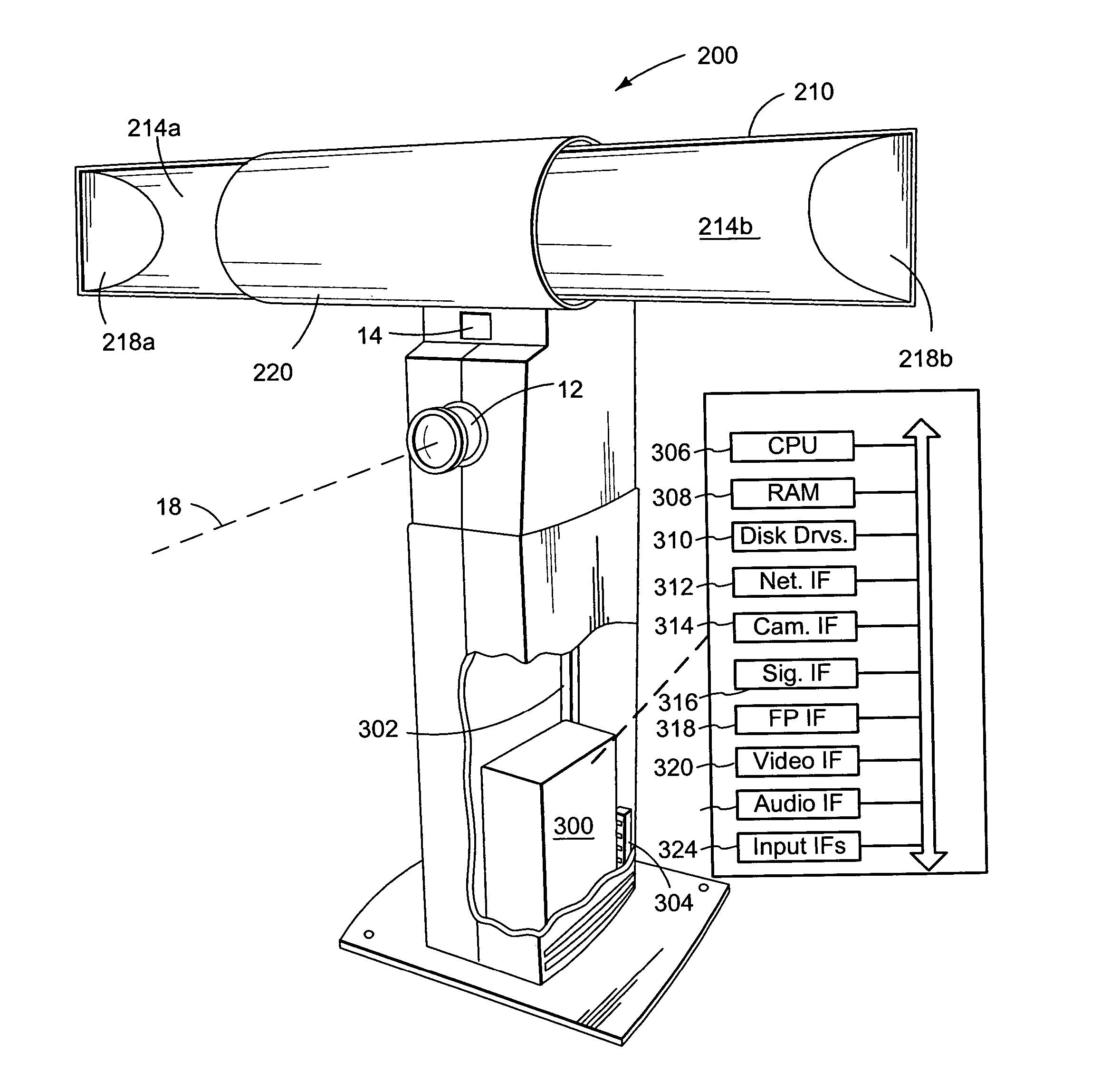
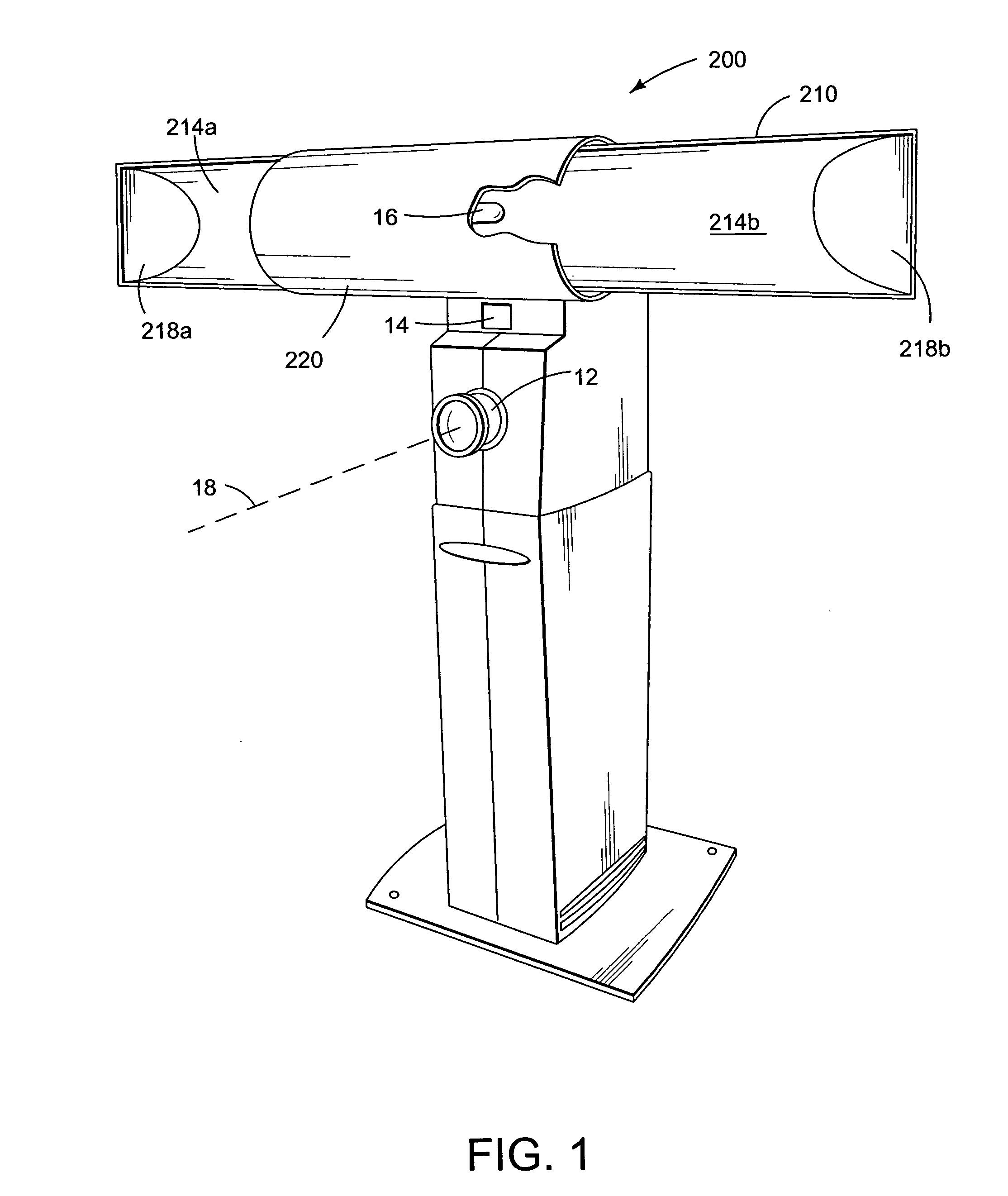
[0022]FIG. 1 illustrates a capture station 10, that includes an image capture device 12, such as a video camera and lens, a light sensor 14, and an light source 16 (element 220 is drawn with a break away to reveal the light source). In operation, the capture station 10 is controlled by built in computer (detailed below) to provide light directed toward a subject (applicant for identification document) and to capture a digital image of the subject. Together, the light sensor 14, and a light source 16 operate as a lighting device. An exit aperture plane can be defined to include the surface of the light source 16 through which the light is directed. The image capture device 12 has an observation axis 18 that is orthogonal to the exit aperture plane of the light source 16. In one embodiment, the light sensor 14 is provided by a strobe sensor, and the light source 16 is an electronic strobe. The light sensor 14 provides a real time adjustment to the light source 16 illumination of the s...


PUM


Abstract

An all in one capture station for creating photo identification documents combines the functions of a camera assembly and computer workstation into a single device. This device can be operated in a shared mode where it is controlled via one or more other workstations, or a stand alone mode, where it performs all of the functions needed to prepare an identification document. The all in one capture station includes a camera stand, a camera mounted within the camera stand, and a computer integrated into the camera stand. The computer includes a processor, network interface device, and memory. The memory stores a camera control program and a network interface program for transferring camera control commands and image data between the capture station and a remote workstation so that the capture station can operate under the control of the remote workstation to capture data for incorporation into an identification document.

Description

FIELD OF THE INVENTION [0001] The invention relates to a capture station and related systems and methods for creating identification documents. BACKGROUND AND SUMMARY [0002] In typical systems for capturing photos for identification documents, the camera assembly and workstation used to control it are separate devices. This type of capture configuration is more difficult to transport and configure in an office setting and is more costly because it involves two physically separate machines. It also presents challenges in sharing the capture station among more than one station operator, adding cost and inconvenience. [0003] In one approach to enable sharing of the camera assembly, the workstation that controls the camera assembly may be connected to other workstations in a computer network. This network configuration enables the other workstations to issue image capture and transfer commands to the workstation directly connected to the capture stand. However, this configuration presen...

Claims


Application Information

Patent Timeline
Patent Type & Authority Applications(United States)
IPC IPC(8): G06KG07C9/00H04N1/00H04N5/225
CPCG07C9/00087G07C2209/41H04N1/00204H04N1/00286H04N2201/0084H04N5/2252H04N5/2256H04N2201/001H04N1/00289G07C9/257H04N23/56H04N23/51
Inventor DUGGAN, CHARLES F.KENEN, LEO M.SCHNECK, NELSONBOHAKER, DAVID
Owner DIGIMARC CORP
Why Eureka
Eureka Blog
Learn More