
Direction-recognizing apparatus, direction-recognizing method, direction-recognizing system, and robot apparatus

a robot and position recognition technology, applied in the direction of instruments, manufacturing tools, image data processing, etc., can solve the problems of not being able to accurately detect the position of the robot, inevitably taking a long time to detect the robot position, and the position detection method is not suitable for entertainment robots, so as to achieve the effect of efficient approach

Inactive Publication Date: 2005-03-31
SONY CORP
View PDF2 Cites 44 Cited by
  • Summary
  • Abstract
  • Description
  • Claims
  • Application Information

AI Technical Summary

Benefits of technology

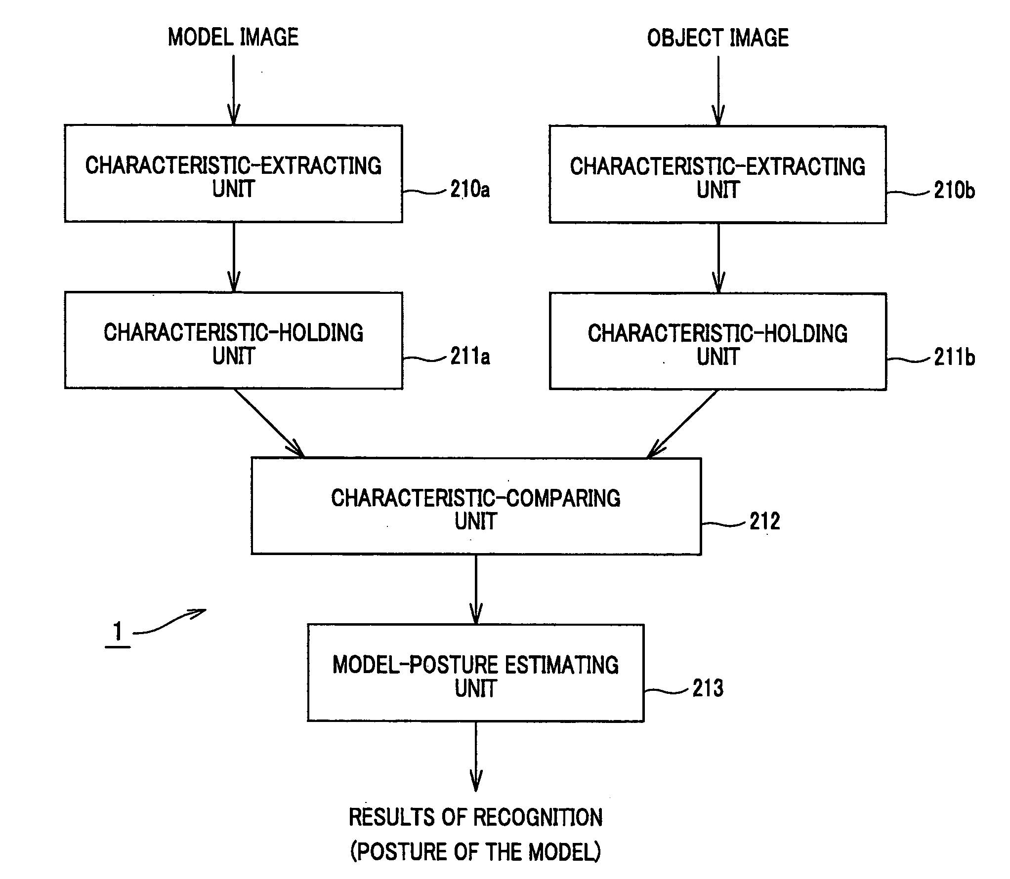
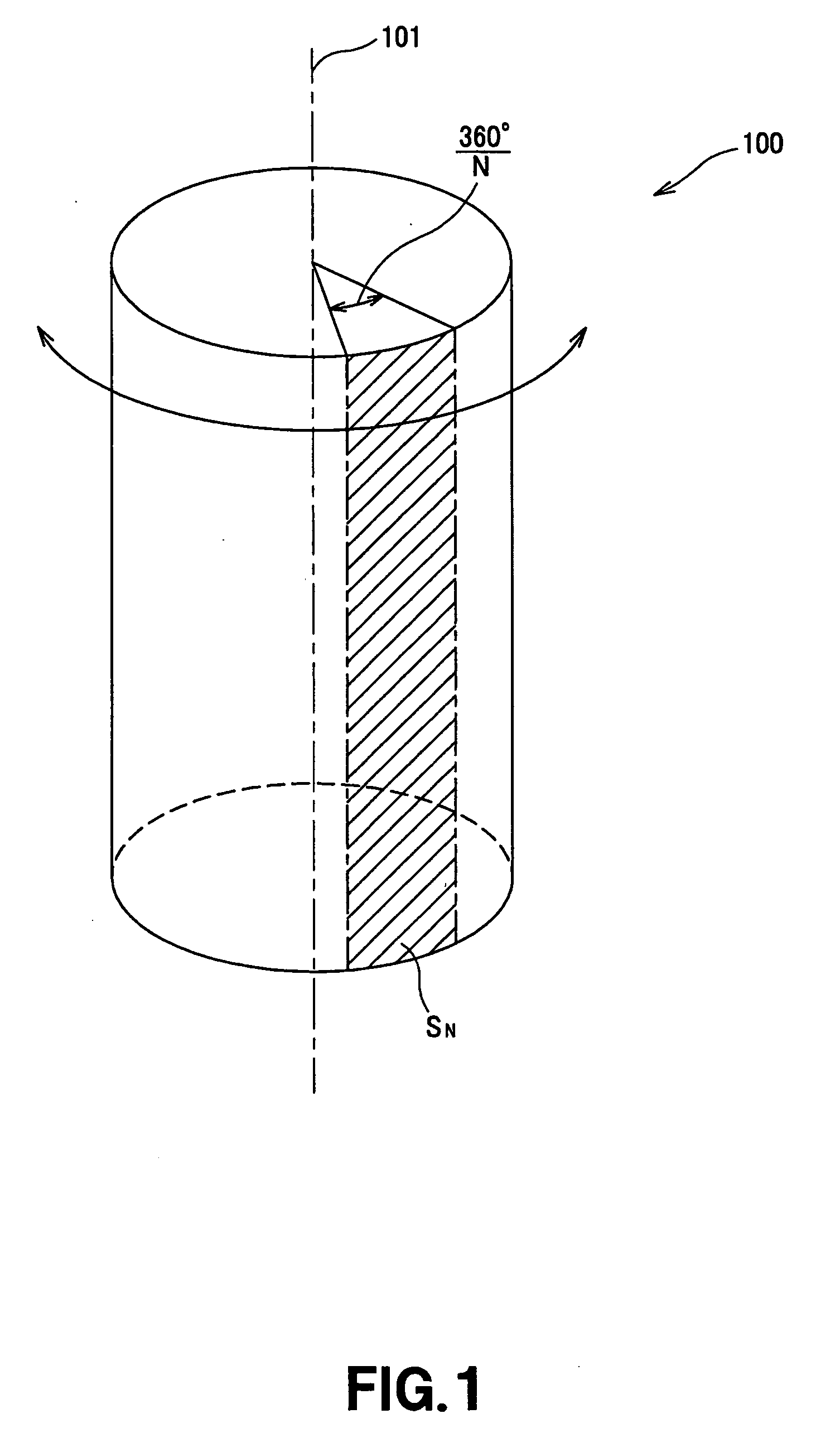
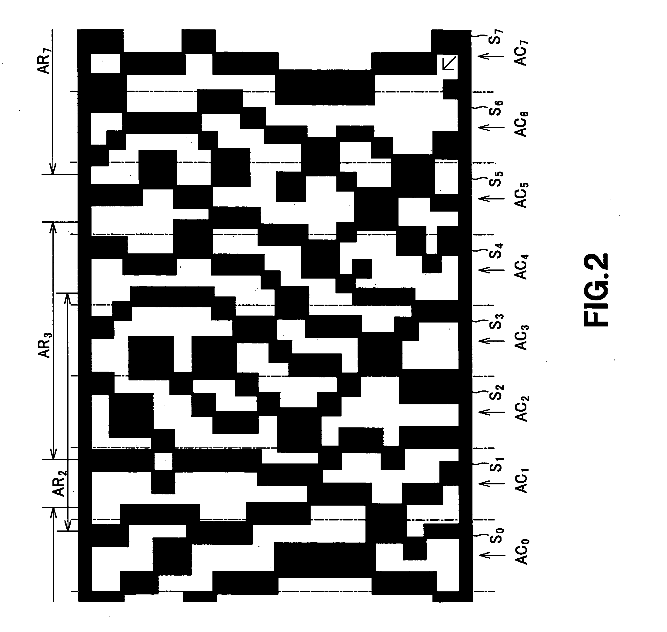
The registered images include the images of the N surface segments of the direction-indicating member, respectively, and are larger than the images of the N surface segments obtained by dividing the surface of the direction-indicating member by N. They are used to identify surfaces, each being larger than a 360° / N surface segment, where 360° is the circumference of the direction-indicating member. Since the registered images are larger than the images of the N surface segments, the apparatus can recognize directions at higher accuracy than otherwise.
The direction-recognizing apparatus may be incorporated in a robot apparatus. Then, the robot apparatus can recognize the direction in which any image input to it has been photographed. The robot apparatus may have a distance sensor, for example, which detects the distance to an object. Then, the robot apparatus can efficiently approach the object in accordance with the direction recognized and the distance detected. This can make the robot apparatus look intelligent.

Problems solved by technology

If one landmark, for example, cannot be found, it is no longer possible to detect the position of the robot correctly.
Since all landmarks must be recognized, it inevitably takes a long time to detect the position of the robot.
In view of this, the position-detecting method is not fit for use in entertainment robots.

Method used


Image

  • Direction-recognizing apparatus, direction-recognizing method, direction-recognizing system, and robot apparatus
  • Direction-recognizing apparatus, direction-recognizing method, direction-recognizing system, and robot apparatus
  • Direction-recognizing apparatus, direction-recognizing method, direction-recognizing system, and robot apparatus

Examples


Embodiment Construction

An embodiment of the present invention will be described in detail, with reference to the accompanying drawings. This embodiment is a two- or four-legged robot apparatus. The robot apparatus incorporates a direction-recognizing apparatus that can determine the direction of an object.

The direction-recognizing apparatus and the robot apparatus use a direction-indicating member to recognize the direction of an object. The direction-indicating member and the direction-recognizing apparatus that uses the member will be first described. Then, an appropriate technique employed in the apparatus to recognize directions will be explained. Finally, the robot apparatus having the direction-recognizing apparatus will be described.

(1) Direction Recognition by the Direction-Indicating Member

The direction-indicating member that helps a moving body, such as a robot apparatus, to recognize directions. The direction-indicating member has a pattern printed on it. If the camera on the body (e.g.,...


PUM


Abstract

A direction-recognizing apparatus has a photographing unit, an image database, an image-recognizing unit, and a direction-recognizing unit. The database stores registered images and direction-data items associated with the registered images. The image-recognizing unit receives an input image and compares the input image with the registered images stored in the database. The image-recognizing unit selects one registered image that is identical or similar to the input image. The direction-recognizing unit recognizes a direction from the direction data associated with the registered image selected by the image-recognizing unit. The database may store N direction-data items associated with N surface segments SN of the circumferential surface of a pole 100. If so, the images registered in the database represent direction-recognition regions ASN that are larger than the N surface segments SN.

Description

BACKGROUND OF THE INVENTION 1. Field of the Invention The present invention relates to a direction-recognizing apparatus and a direction-recognizing method, in which a direction-indicating member recognizes a direction from an image input to it. The invention relates to a direction-recognizing system, too, which comprises a direction-indicating member and a direction-recognizing apparatus. The invention also relates to a robot apparatus that has a direction-recognizing apparatus. 2. Description of the Related Art Any apparatus that is electrically or magnetically drive to move like a man (animal) is called “robot.” It is in 1960s that robots came into wide use. Most of them were industrial robots such as manipulators and transportation robots, which are designed to achieve automation or to save labor. Recently, so-called “service robots” have been developed. They are designed to act as living partners to people, assisting and supporting people in social life and daily life. Unl...

Claims


Application Information

Patent Timeline
Patent Type & Authority Applications(United States)
IPC IPC(8): G01B11/26B25J5/00B25J19/02G05D1/02G06K9/00G06T1/00G06T7/00G06T7/60
CPCG06K9/00664G06T7/0044G06K2009/3225G06K9/3216G06T7/74G06V20/10G06V10/245
Inventor MORISADA, HIDEHIKOTSURUMI, SHINGO
Owner SONY CORP
Learn More