Method of processing red eye in digital images

a technology of digital images and red eyes, applied in image enhancement, image analysis, instruments, etc., can solve the problems of insufficient red eye detection, limited technique, and even more severe red eye problems in digital images, and achieve the effect of automatically eliminating the red eye effect and high precision in the localization of red eyes

Inactive Publication Date: 2005-03-31
PRIMAX ELECTRONICS LTD
View PDF6 Cites 9 Cited by
  • Summary
  • Abstract
  • Description
  • Claims
  • Application Information

AI Technical Summary

Benefits of technology

It is therefore an object of the invention to provide a method of processing red eyes in digital images that can overcome the problems of the prior art. According to the invention, the method of pr...

Problems solved by technology

With the flash lamp being closer to the camera objective lens, the problem of red eye is even more severe.
Although some more advanced cameras are promoted as having anti-red eye operating modes, the problem of red eye is still common in digital images.
However, this technique has limited results, and is not really able to completely eliminate the appearance of red eyes.
As a ...

Method used


Image

  • Method of processing red eye in digital images
  • Method of processing red eye in digital images
  • Method of processing red eye in digital images

Examples


second embodiment

The flowchart of FIG. 4 schematically illustrates a method of processing red eye in a digital image according to the invention. First, a skin color area of the image is detected (step 410). The skin color area is typically determined from the range of HIS parameters. Then a visage area is localized in the skin color area (step 420). In an image, the visage area is the largest area of a skin color area. To determine the visage area, the number of pixels and the number of pixel rows in the skin color area are evaluated: if the skin color area has a number of pixels greater than a pixel number reference and a number of pixel rows greater than a row number reference, the corresponding closed area is considered as a visage area. Usually, a visage area has a number of pixels greater than 5000, and a number of pixel rows greater than 100. Once the visage area has been determined, other skin color area with fewer pixels such as the arms can be filtered out, and the red eye then is searched ...

third embodiment

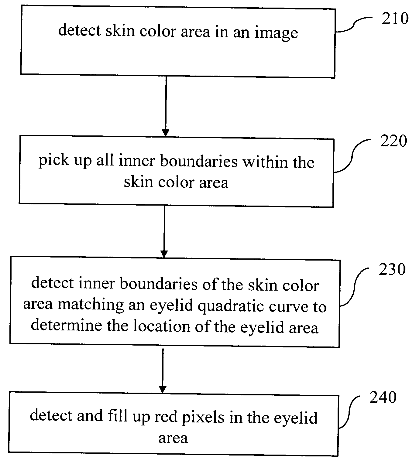
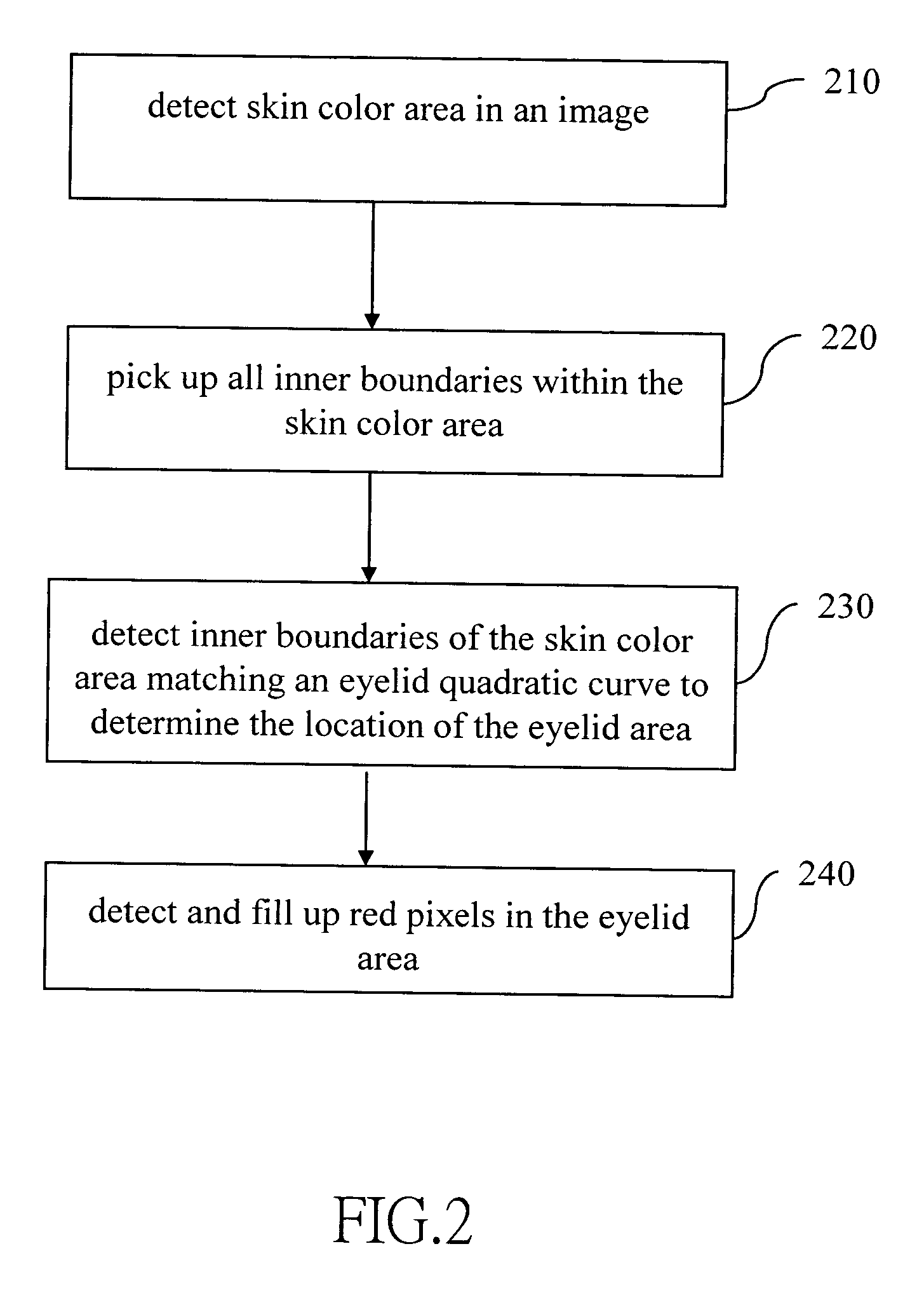
The flowchart of FIG. 5 schematically illustrates the invention. First, a skin color area is detected in the image (step 510). A skin color area is typically determined from the range of HIS parameters. Subsequently, all inner boundaries in the skin color area are picked up (step 430).Inner boundary determination can be performed by evaluating the gray scale gradients of a gray scale image in the same manner as described above. Alternatively, a peripheral edge detection technique can be used to determine the inner boundaries of the skin color area. Then, the inner boundaries of the skin color area matching eyelid quadratic curves are determined. In particular, the eyelid quadratic curves are expressed as follows: Y=aX2+bX+c, wherein if 0.01<−a<0.05 the quadratic curve is an upper eyelid quadratic curve, and if 0.01<a<0.05 the quadratic curve is a lower eyelid quadratic curve. Two boundaries that respectively correspond to the upper and lower eyelid quadratic curv...

fourth embodiment

The flowchart of FIG. 6 schematically illustrates the invention. First, a skin color area is detected in the image (step 610). Then the visage area is detected in the skin color area (step 620). All inner boundaries in the visage area are subsequently detected (step 630). The inner boundaries of the visage area are matched with the eyelid quadratic curve to determine the proper upper and lower eyelid quadratic curves. Horizontal coordinate error between the respective apexes of the matched quadratic curves is then evaluated; if the apex horizontal coordinate error is smaller than an apex reference value, the area enclosed by the eyelid quadratic curves is considered an eyelid area (step 640). In this embodiment, the apex reference value is, for example, 4. Subsequently, the inner boundaries of the eyelid area are matched with the iris quadratic curve to determine the iris area (step 650). Lastly, red pixels in the iris area are localized and filled up (step 660). Incorporating the d...


PUM


Abstract

In a method of processing red eye in digital images, a skin area is first determined in an image. Then all inner boundaries within the skin area are picked up. The inner boundaries are matched with an eyelid quadratic curve to determine the location of the eyelid area. Red pixels within the eyelid area are then detected and filled up. A quadratic curve model can be further used to localize an iris area within the eyelid area to improve the precision of red eye localization as well as the processing speed.

Description

BACKGROUND OF THE INVENTION 1. Field of Invention The invention relates to a method of processing digital images, and more particularly to a method of processing red eye in digital images. 2. Related Art Digital image processing technology has found wide application in the market of electronic appliances. When a digital photo is taken, the eyes of people or animals may appear red on the photo. This is due to the fact that in dark environments, human or animal eye pupils are more dilated and form a greater open area. Therefore, a flash for which the light axis is closer to the light axis of the camera objective lens will likely reflect on the back of the eye of the photographed subject toward the objective lens. The back of the eye is usually full of red capillaries, which make the subject's eye appear as a red spot on the photo. As new generations of cameras are promoted, it can be observed that the distance that separates the flash lamp from the camera objective lens is decrea...

Claims


Application Information

Patent Timeline
IPC IPC(8): G06K9/00G06K9/34G06T5/00G06T7/40
CPCG06K9/0061G06T7/0089G06T7/408G06T2207/10024G06T2207/30201G06T2207/30216G06T5/005G06T2207/20116G06T7/149G06T7/90G06V40/193
Inventor WU, SHANG-YUN
Owner PRIMAX ELECTRONICS LTD
Why Eureka
Try Eureka