Optical transceiver over single communication link

a technology of optical transceivers and communication links, applied in the field of optical communication systems, can solve the problems of increasing the cost of bi-directional communication with two fibers

Inactive Publication Date: 2005-03-31
INTEL CORP
View PDF6 Cites 37 Cited by
  • Summary
  • Abstract
  • Description
  • Claims
  • Application Information

AI Technical Summary

Problems solved by technology

Thus, the two-fiber solution achieves bi-directional communications at an increased cost, both in terms of an initial infrastructure investment and maintenance.

Method used


Image

  • Optical transceiver over single communication link
  • Optical transceiver over single communication link
  • Optical transceiver over single communication link

Examples


Embodiment Construction

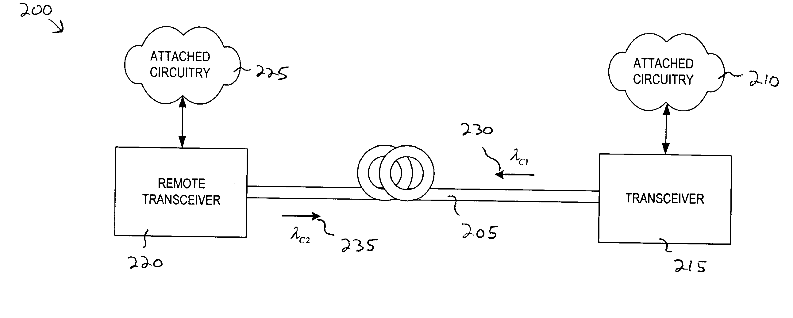
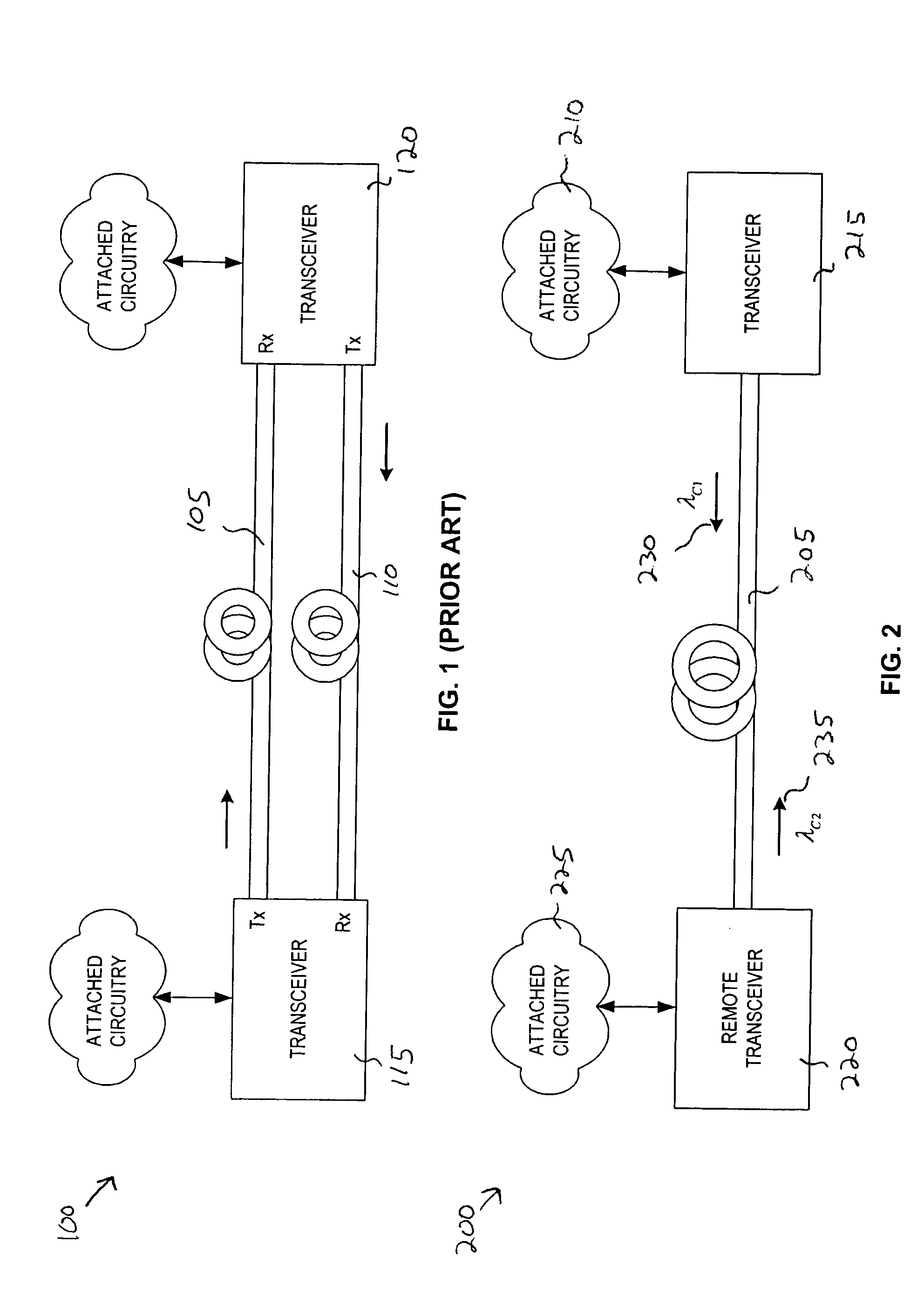
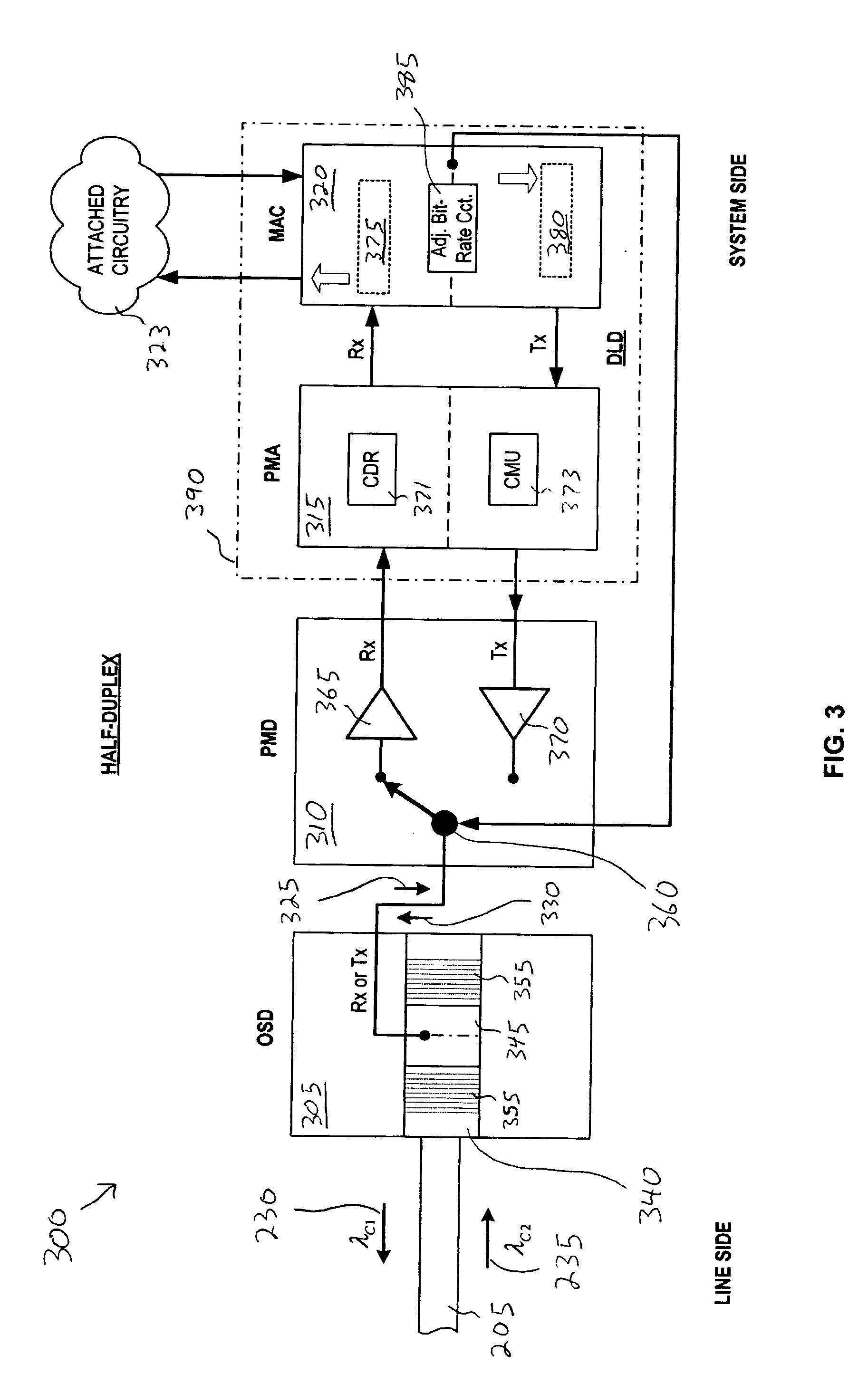
[0016] Embodiments of a system and method for optical communications across a single communication link (e.g., optical fiber) are described herein. In the following description numerous specific details are set forth to provide a thorough understanding of embodiments of the invention. One skilled in the relevant art will recognize, however, that the invention can be practiced without one or more of the specific details, or with other methods, components, materials, etc. In other instances, well-known structures, materials, or operations are not shown or described in detail to avoid obscuring aspects of the invention.

[0017] Reference throughout this specification to “one embodiment” or “an embodiment” means that a particular feature, structure, or characteristic described in connection with the embodiment is included in at least one embodiment of the present invention. Thus, the appearances of the phrases “in one embodiment” or “in an embodiment” in various places throughout this sp...


PUM


Abstract

A method, apparatus, and system for optical communications. An optical transmit signal is generated in response to an electrical transmit signal. The optical transmit signal is coupled into a single communication link for transmission there over. An optical receive signal is received from the single communication link, and in response an electrical receive signal is generated.

Description

TECHNICAL FIELD [0001] This disclosure relates generally to optical communication systems, and in particular, but not exclusively, relates to electro-optical transceivers. BACKGROUND INFORMATION [0002] Modern communication tools and applications are demanding higher and higher bandwidths to support increasing data throughputs. A popular solution to support the data throughput demands are optical communication networks. Optical communication networks are capable of supporting data bit-rates on the order of Gbits / s using a single optical fiber. [0003] However, most modern communication tools and applications require bi-directional communications. Thus, optical communication networks must be capable of supporting bi-directional communications. FIG. 1 is a block diagram illustrating a known bi-directional optical communication system 100. Optical communication system 100 is a two-fiber solution. Optical communication system 100 addresses the bi-directional problem by providing two unidi...

Claims


Application Information

Patent Timeline
Patent Type & Authority Applications(United States)
IPC IPC(8): H04B10/24
CPCH04B10/2503H04B10/2589
Inventor FRANCK, THORKILDJOHANSEN, EIVINDCHRISTENSEN, BENNYLOBEL, MARTIN
Owner INTEL CORP
Why Eureka
Try Eureka