Fuel cell

Inactive Publication Date: 2005-03-31
KK TOSHIBA
View PDF8 Cites 7 Cited by
  • Summary
  • Abstract
  • Description
  • Claims
  • Application Information

AI Technical Summary

Benefits of technology

[0003] The present invention relates to a fuel cell usable as a power source for an electronic device or the like and an electronic device provided with the same.
[0010] The accompanying drawings, which are incorporated in and constitute a part of the specification, illustrate embodiments of the invention, and together with the general description given above and the detailed description of the embodiments given below, serve to explain the principles of the invention.

Problems solved by technology

These modern electronic devices have increasingly higher functions and require increased power consumption and longer operating time.
If the semiconductor devices are overheated, they may undergo malfunction or failure.
If it is positively circulated around the electronic components, therefore, metallic parts of the control circuit section may suffer corrosion or short-circuiting.
Thus, it is hard to control the generator section normally, so that the reliability of the fuel cell lowers.

Method used


Image

  • Fuel cell
  • Fuel cell
  • Fuel cell

Examples


second embodiment

[0053] The following is a description of a personal computer with a fuel cell, as an electronic device according to the invention. According to the present embodiment, the personal computer and the fuel cell are formed integrally with each other. As shown in FIG. 9, a personal computer 100 is provided with a housing 102. The housing 102 has a device body 104, a cell body 106, and a partition wall 105 that internally divides the bodies 104 and 106.

[0054] A second region that is defined by the device body 104 houses a control circuit board 108 that constitutes a control section 107 of the personal computer 100. A CPU 110 for use as a heat generating electronic component is mounted on the control circuit board.

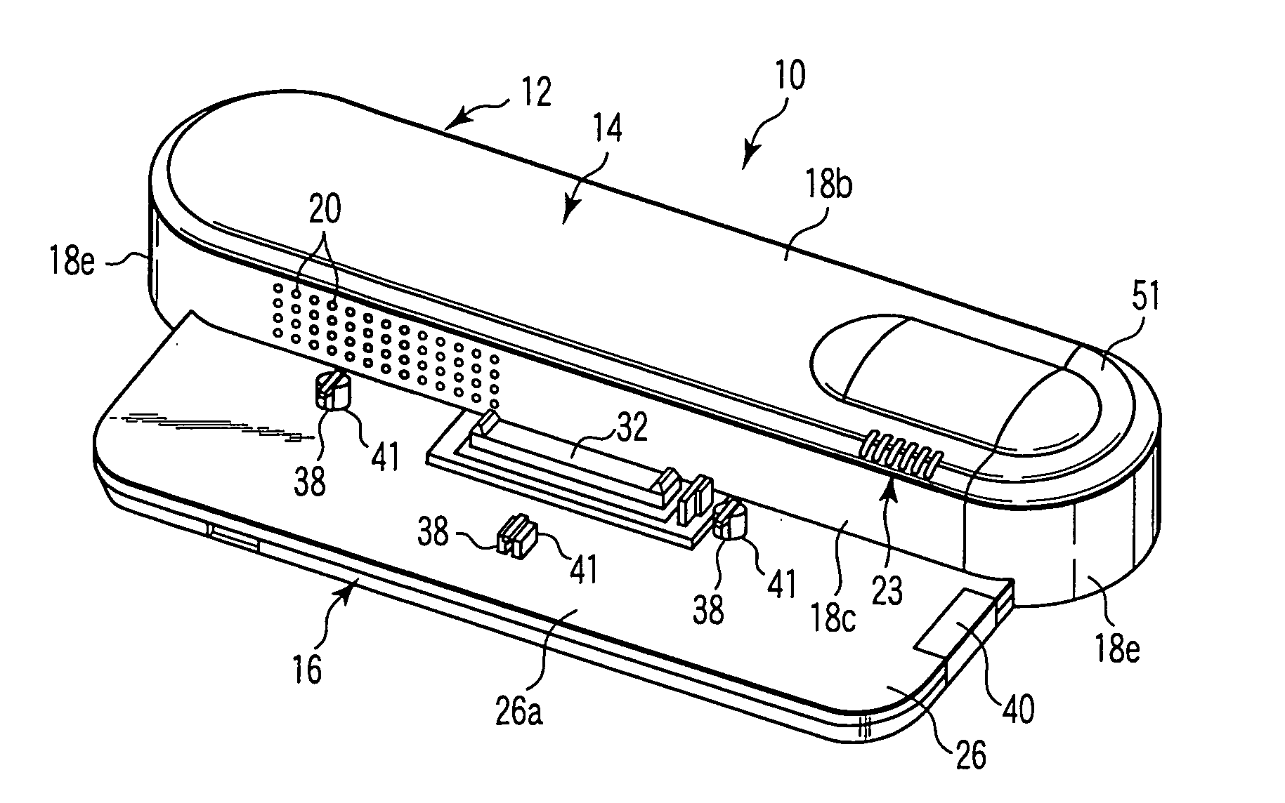
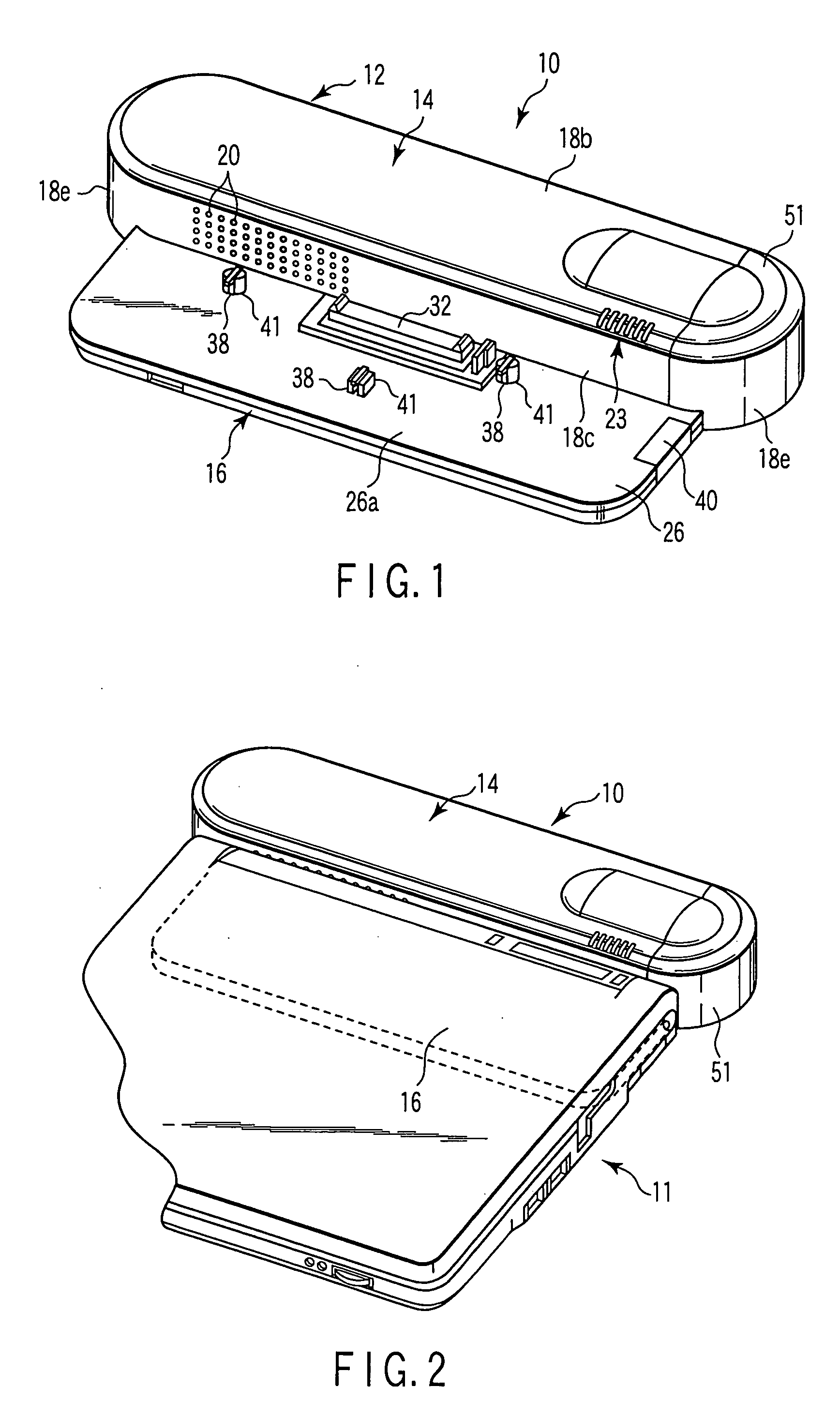
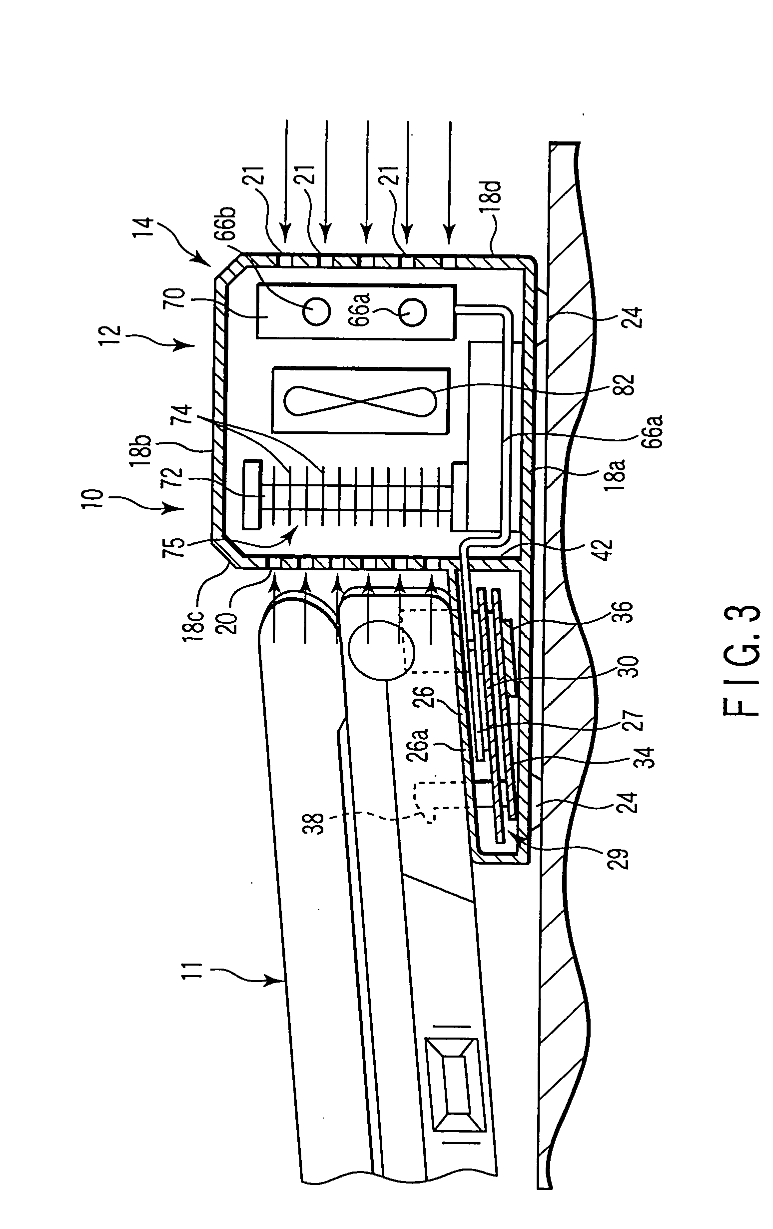
[0055] As in the first embodiment described above, on the other hand, the cell 106 has a rear wall 18d formed with vents 21 and sidewalls 18e with vents 22. Vents 20 are formed in the partition wall 105. The fuel cell comprises a generator section 7 located in a first region tha...

first embodiment

[0060] A discharge pipe is connected to the electromotive unit 52 and forms a cathode passage through which products of power generation from the cathodes of the cells and air are discharged. The cathode passage, like the one has a first passage, branch passages 72b, reservoir portion, recovery passage, and second passage 72e. The recovery passage guides water stored in the reservoir portion into the mixing tank 54. The second passage 72e communicates with the respective upper ends of the branch passages. The recovery passage is provided with a recovery pump that supplies the water in the reservoir portion to the mixing tank 54. A large number of horizontally extending radiator fins are mounted around the discharge pipe that forms the branch passages, and constitute a second radiator section 75.

[0061] The second radiator section 75 is opposed substantially parallel to the first radiator section 70 with a gap between them. The second passage 72e extends substantially horizontally an...


PUM


Abstract

A generator section and a control section are arranged in a housing of a fuel cell. The generator section has an electromotive unit which generates power based on a chemical reaction, a fuel tank which contains a fuel, a fuel circulation passage through which the fuel is circulated between the electromotive unit and the fuel tank, and a radiator section which cools the fuel circulation passage. The control section has a heat generating electronic component and controls the operation of the generator section. A part of the fuel circulation passage is connected thermally to the heat generating electronic component.

Description

CROSS-REFERENCE TO RELATED APPLICATIONS [0001] This application is based upon and claims the benefit of priority from prior Japanese Patent Application No. 2003-342337, filed Sep. 30, 2003, the entire contents of which are incorporated herein by reference. BACKGROUND OF THE INVENTION [0002] 1. Field of the Invention [0003] The present invention relates to a fuel cell usable as a power source for an electronic device or the like and an electronic device provided with the same. [0004] 2. Description of the Related Art [0005] Currently, secondary batteries, such as lithium ion batteries, are mainly used as power sources for electronic devices, such as portable notebook personal computers, mobile devices, etc. These modern electronic devices have increasingly higher functions and require increased power consumption and longer operating time. To meet these requirements, compact, high-output fuel cells that require no charging are expected as novel power sources. Various types of cells ex...

Claims


Application Information

Patent Timeline
IPC IPC(8): H01M8/02H01M8/04H01M8/24
CPCH01M8/04007H01M8/04029H01M8/04074H01M8/04156Y02B90/18H01M8/2475H01M2250/30Y02E60/50H01M8/247Y02B90/10
Inventor TOMIOKA, KENTAROSATO, YUUSUKETAJIMA, NOBUYASU
Owner KK TOSHIBA
Why Eureka
Try Eureka