
Terminal state control system

a control system and terminal technology, applied in the field of network systems, can solve the problems of difficult to distinguish with ease, difficult to install many antennas in a narrow area, and difficult to install base stations of imcs or simple imcs described above only for the convenience of mobile telephone companies

Inactive Publication Date: 2005-03-31
FUJITSU LTD
View PDF16 Cites 159 Cited by
  • Summary
  • Abstract
  • Description
  • Claims
  • Application Information

AI Technical Summary

Benefits of technology

[0015] Further, another object of the present invention is to provide a technique with which it becomes possible for a user to know whether his / her terminal allowed to use a specific base station exists in a cell of the specific base station. Further, another object of the present invention is to provide a technique with which a terminal can perform as much communication as possible using a specific base station at which the terminal is registered.
[0016] Further, another object of the present invention is to provide a technique with which, as to a certain terminal, it becomes possible to distinguish with ease between communication using a specific base station at which the terminal is registered, and communication using another base station.
[0044] Also, according to the present invention, it becomes possible for a user to know whether his / her terminal allowed to use a specific base station exists in a cell of the specific base station. Further, according to the present invention, it becomes possible to provide a technique with which a terminal can perform as much communication as possible using a specific base station at which the terminal is registered.
[0045] Also, according to the present invention, as to a certain terminal, it becomes possible to distinguish with ease between communication using a specific base station at which the terminal is registered, and communication using another base station.

Problems solved by technology

With the simple IMCS, however, when the proxy antenna emits a strong radio wave, there is a possibility that other terminals in the same area may be adversely affected due to radio wave interferences, so that it is impossible to install many antennas in a narrow area.
Therefore, it is of course impossible to install a base station of the IMCS or the simple IMCS described above only for the convenience of the mobile telephone companies.
Also, even if an individual inversely desires installation of a private-house-use (personal-use or home-use) base station, it is impossible to personally purchase and install the base station under the current circumstances from the viewpoints of cost and space.
Therefore, it is likely that the mobile telephone company requests him / her to bear the cost of the installation of the base station system in some manner.
In other words, when an individual introduces a base station, if another person existing in a range where it is possible to receive a ratio wave from the base station is allowed to use the base station, such a situation arises that when the individual tries to perform communication using the base station, the line of the base station is already busy because the other person is using it, and therefore the individual cannot perform communication.

Method used


Image

  • Terminal state control system
  • Terminal state control system
  • Terminal state control system

Examples


embodiment 1

[0243] [Embodiment 1]

[0244] Next, as Embodiment 1 of the first embodiment mode of the present invention, processing (location registration) in the case where the registration table is arranged in a VLR will be described. FIGS. 14A and 14B show the layered LAIs in the first example, FIGS. 15A, 15B, 16A, and 16B each concretely show VLR / HLR registration contents in the first example, and FIGS. 17 to 26 are each a sequence diagram showing processing executed when a terminal A or B shown in FIG. 14 moves to any one of points 1> to 6> in FIG. 14 (corresponding to the points “J” to “N” in FIG. 10).

[0245] In FIG. 14A, as the first example, there is shown an access network (UTRAN) containing an LA allocated an LAI=10 and having a conventional system structure, and an LA allocated an LAI=20 and having a structure according to the present invention.

[0246] The LA having the LAI=20 contains a new RNC (NRNC) 1 serving as a base station control apparatus according to the present invention, and ...

embodiment 2

[0315] [Embodiment 2]

[0316] Next, as Embodiment 2 in the first embodiment mode of the present invention, processing (location registration) in the case where the registration table is arranged in the NRNC will be described. FIGS. 27A and 27B show a network structure in Embodiment 2, FIGS. 28A, 28B, 29A, and 29B each concretely show the VLR / HLR registration contents in Embodiment 2 and the registration table provided for the NRNC, and FIGS. 30 to 38 are each a sequence diagram showing processing executed in the case where the terminal A or B shown in FIG. 27A exists at each one of points 1> to 6> shown in FIG. 27A (corresponding to the points “J” to “N” in FIG. 10).

[0317] The network of Embodiment 2 shown in FIG. 27A has the same structure as the network of Embodiment 1 shown in FIG. 14A. In Embodiment 2, however, the network structure is changed so that an NRNC 4 is provided with a conversion table 5 and has a registration table 6 (FIGS. 14B, 28B and 29B) in place of the VLR 2. Acc...

second embodiment

[0431] [Effect of Second Embodiment Mode]

[0432] According to the second embodiment mode, it is possible to obtain the following effects. (1) The registration table is used for a judgment about the transmission destination of a call termination message, so that it becomes possible to reduce the processing for transmitting unnecessary call termination messages and to alleviate loads placed on the apparatuses on the core network side, the base station management apparatuses, and the lines therebetween. (2) Information showing a base station, via which a call termination message should be transmitted to a destination, is added to the message, so that it becomes possible to eliminate the processing for transmitting unnecessary call termination messages from a base station management apparatus to base stations other than the destination base station and to alleviate loads placed on the base station management apparatus, the base stations, and the lines therebetween. (3) The registration t...


PUM


Abstract

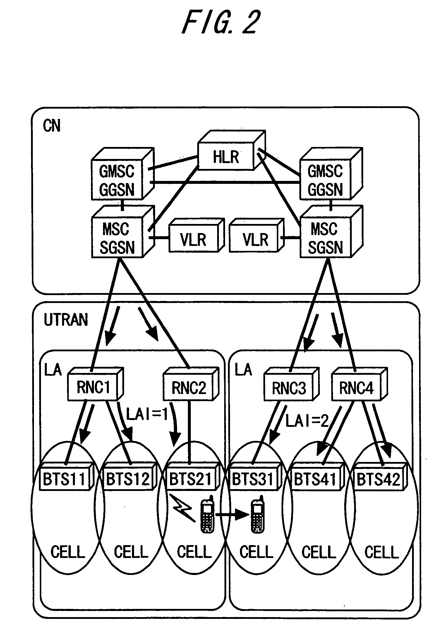
When a terminal enters a cell of a personal-use base station (NBTS) arranged in a certain location area, the terminal receives a location area identifier having a number that is different from an identifier of the location area, and transmits a location updating request with the reception of the location area identifier as a trigger. On receiving the location updating request, a VLR or an NRNC having a registration table, in which the ID of the personal-use base station and the ID of a terminal allowed to use the personal-use base station are registered, judges whether the terminal issued the location updating request is the terminal allowed to use the personal-use base station by referring to the registration table. If the terminal issued the location updating request corresponds to the terminal allowed to use the personal-use base station, the terminal is placed under a status where it is capable of performing communication in the cell, and if not, the terminal is placed under a status where it is incapable of performing communication in the cell.

Description

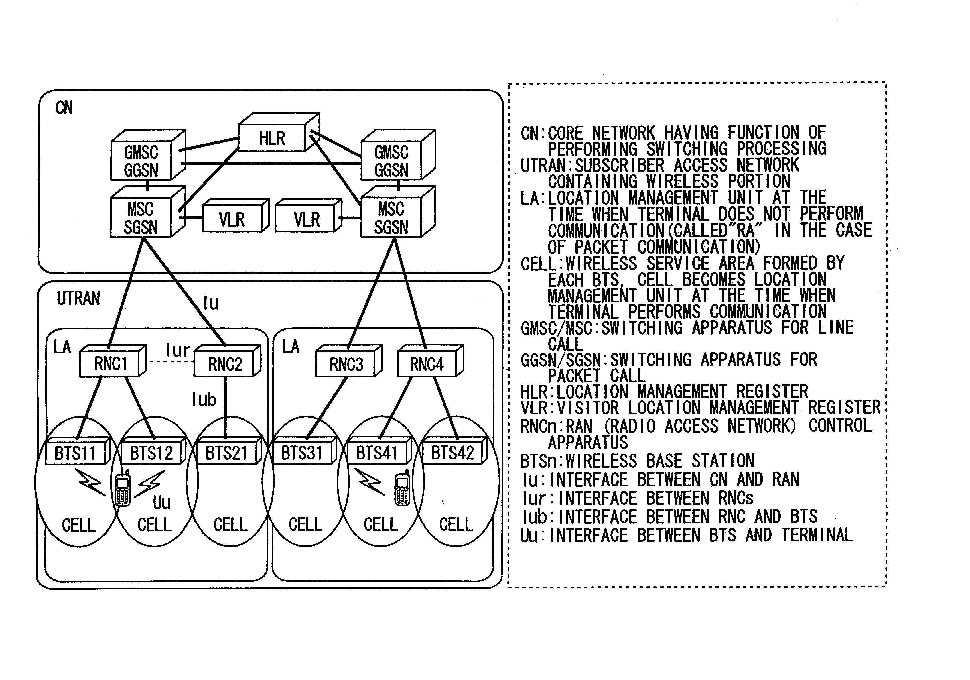
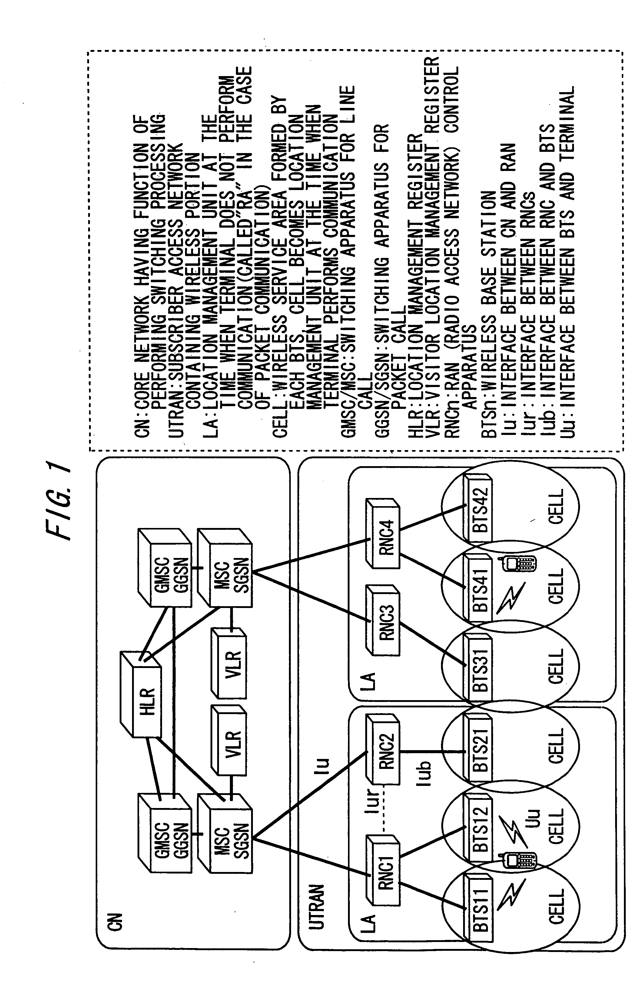
BACKGROUND OF THE INVENTION [0001] 1. Field of the Invention [0002] The present invention relates to a network system that performs state control of a mobile terminal. [0003] 2. Description of the Related Art [0004] In a mobile telephone service, there exists a region that is set as a service area in a map but is out of reach of a radio wave, that is, an area called “blind zone”. The blind zone exists because radio waves basically travel straight and therefore wireless radio waves from an entrance of a mobile telephone network called “wireless base station” do not reach a mobile terminal existing behind a building, inside a building, in a basement, or the like in usual cases. [0005] In order to eliminate such a blind zone, several new types of wireless base stations have been developed. For instance, there is a system called “optical base station”, where an optical line is laid down so as to extend from an existing base station to an area that becomes a blind zone because the area i...

Claims


Application Information

Patent Timeline
Patent Type & Authority Applications(United States)
IPC IPC(8): H04L12/701H04W8/06H04W12/06H04W36/00H04W36/10H04W40/34H04W48/02H04W48/20H04W60/00H04W60/04H04W84/16H04W92/12H04W92/14
CPCH04W8/06H04W36/10H04W48/02H04W92/14H04W84/105H04W84/16H04W92/12H04W60/04
Inventor HASHIMOTO, MASANORIMIYAZAKI, NAOTEZUKA, YASUOKUNIYOSHI, HIDEKAZU
Owner FUJITSU LTD
Learn More