Eureka AIR delivers breakthrough ideas for toughest innovation challenges, trusted by R&D personnel around the world.

Non-contact patient temperature measurement

Active Publication Date: 2005-03-31
DATEX OHMEDA
View PDF16 Cites 42 Cited by
  • Summary
  • Abstract
  • Description
  • Claims
  • Application Information

AI Technical Summary

Benefits of technology

[0007] Another objective of the present invention is to provide a system that allows a medical technician to readily measure a patient's temperature in a quick and convenient manner.
[0030] In another application, the sensor may also include a memory device. Such a memory device may be of a type that requires no continuous power to retain data (e.g., EPROM memory). Such memory devices may allow data to be stored with the sensor device that may be read each time an interrogation signal is received. For example, prior to application to a patient, such a memory device may be programmed with patient information (e.g., name, room number etc). Additionally, such a memory device may include a factory set calibration value to increase the accuracy of the system. Examples of such memory include read-write memory, write-once / read many memory and read-only memory. As will be appreciated, the type and function of memory incorporated into the sensor device may affect the power requirements of the system as well as the cost of the sensor device.

Problems solved by technology

While the above-noted methods typically provide adequate temperature measurements for diagnostic purposes, each method may be intrusive for a patient and / or difficult for a medical technician to administer as well as require several seconds or minutes per measurement.
This may raise difficulties in cases where a patient is combative, injured, or very young.
Furthermore, periodic measurements may prevent a patient from resting.
Furthermore, such temperature measurement methods may result in a technician contacting a patient's bodily fluids.
However, such hard-wired sensors restrict the movement of a patient and typically must be removed or disconnected to allow a patient to move about (e.g., to a restroom or different site in the hospital).

Method used


Image

  • Non-contact patient temperature measurement
  • Non-contact patient temperature measurement
  • Non-contact patient temperature measurement

Examples


Embodiment Construction

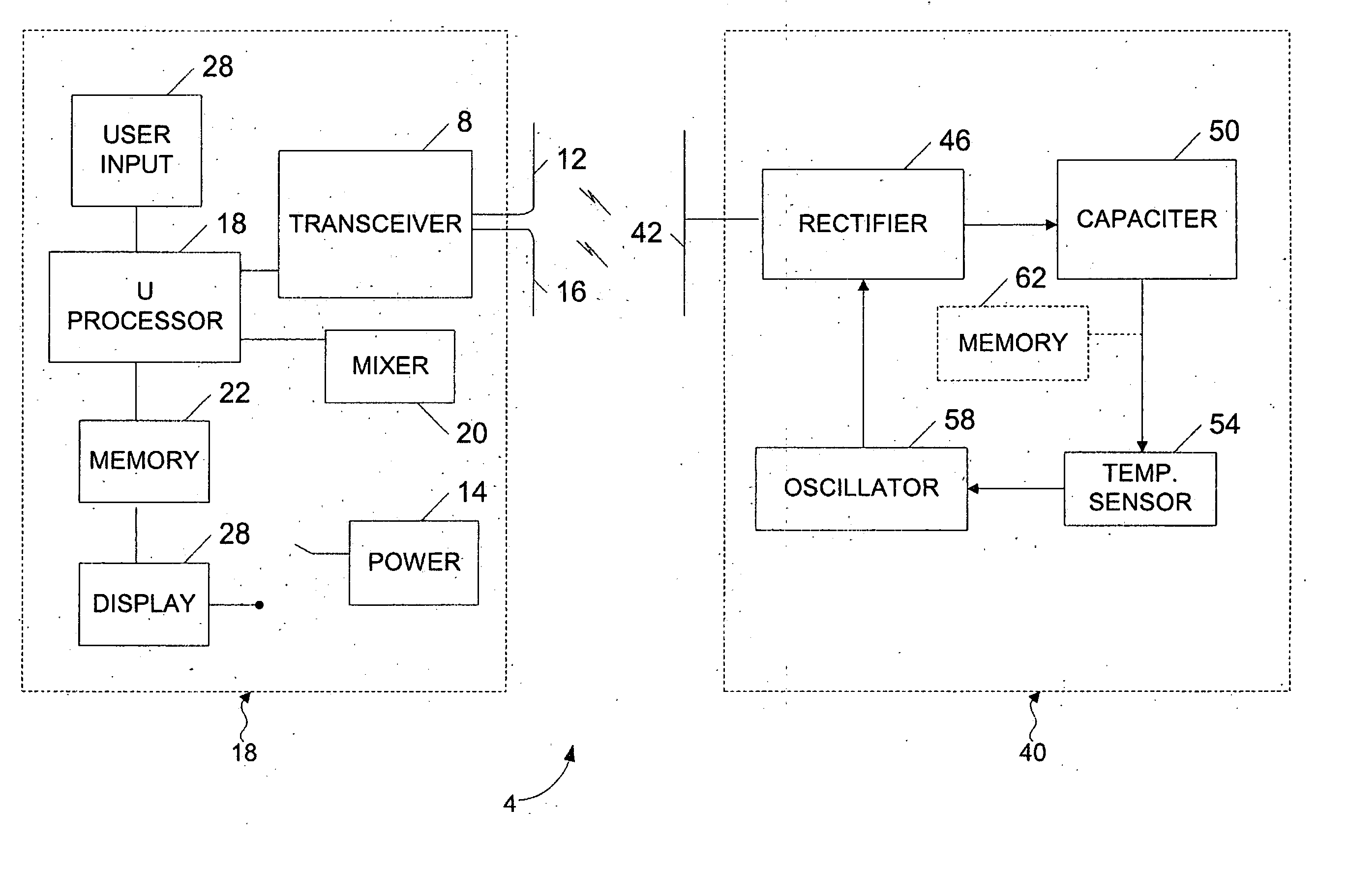
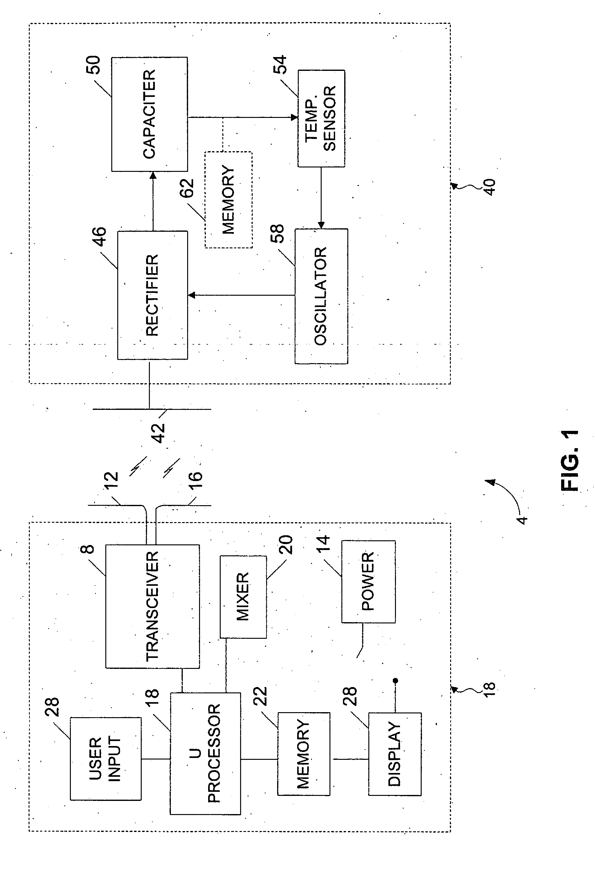
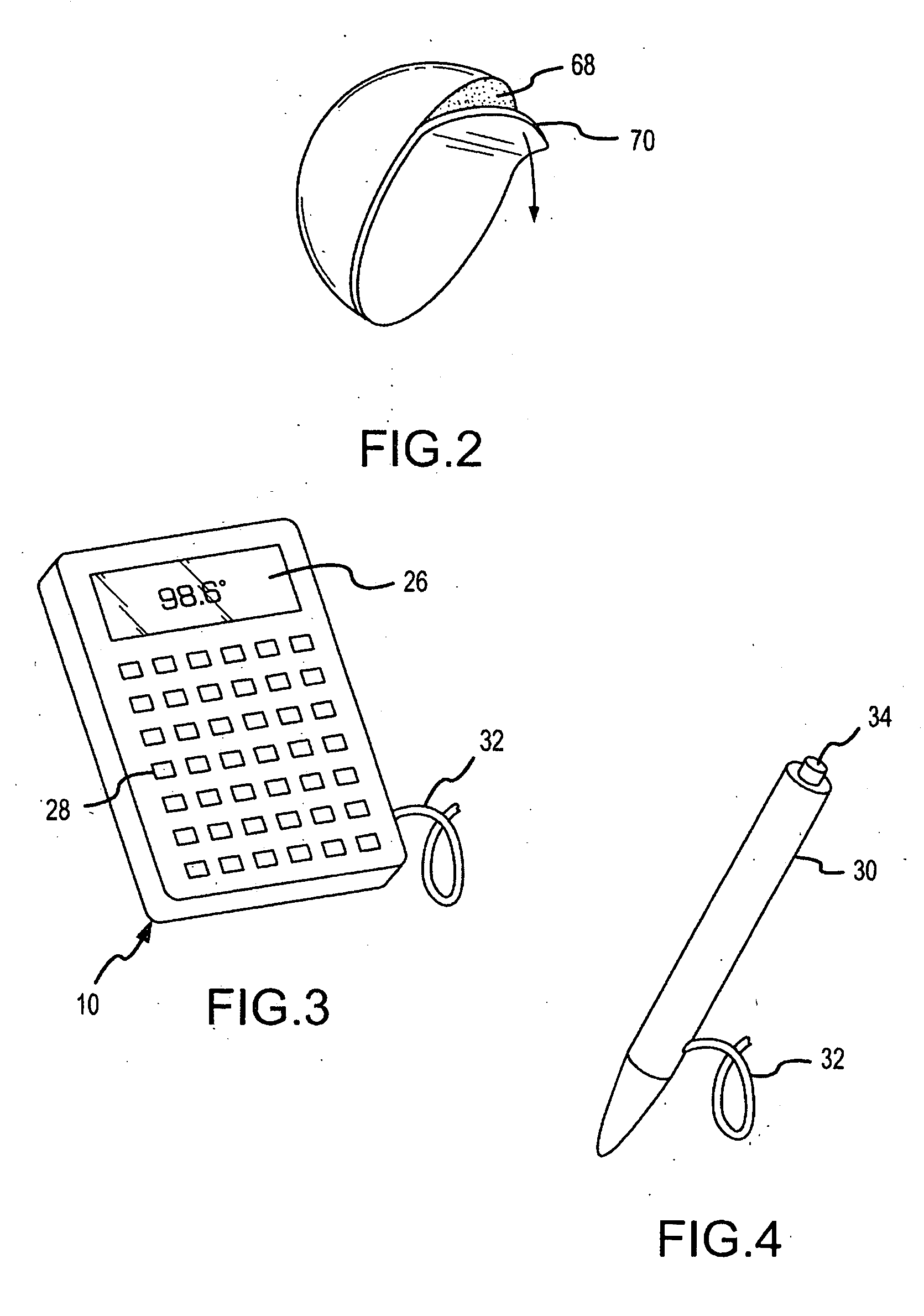
[0039] Disclosed herein is a system and method for non-contact monitoring of a patient's temperature wherein temperature data is transmitted over an air interface. In this regard, a subject (e.g., patient) may wear a temperature sensor that, upon request, transmits the temperature of the patient to a reader over the air interface. More particularly, the system and method utilize a transponder sensor that is able to provide a patient's temperature upon receiving an interrogation signal from a portable reader / probe disposed within a predetermined range of the sensor. In one particular application, the system allows medical personnel, using a portable hand-held reader, to quickly and conveniently measure a patient's temperature without disturbing the patient or raising sanitation concerns.

[0040]FIG. 1 illustrates one embodiment of a radio frequency temperature sensor (RFTS) system 4 that makes use of radio frequency propagation to measure patient temperatures. As will be discussed her...


PUM


Abstract

A method and system are provided for allowing non-contact temperature measurement of an animate body. More particularly, a transponder sensor device attached to an animate body is utilized to non-intrusively measure a temperature of the animate body in response to an interrogation signal transmitted over an air interface from a portable probe. In one embodiment, the sensor device is a passive device that is operative to collect energy from an interrogation signal emitted from the probe. In this regard, the sensor device does not require an internal power source. The collected energy is utilized to measure the temperature of the animate body and transmit a response signal containing temperature information back to the probe over the air interface.

Description

FIELD OF THE INVENTION [0001] The present invention is directed towards a method and system for non-contact temperature measurement of an animate body. More particularly, the invention is directed to utilizing a passive transponder sensor device to obtain a patient temperature in response to an interrogation signal transmitted from a portable hand-held reader. BACKGROUND [0002] In many medical applications, it is desirable to periodically measure the temperature of a patient for diagnostic purposes. In this regard, a variety of temperature measurement devices may be utilized. Such devices include liquid based thermometers (e.g., mercury, alcohol, etc.), infra-red tympanic measurement devices, bi-metal conductors as well as thermally resistive elements (e.g., as used in a digital thermometer). Use of these temperature measurement devices typically requires physically accessing a patient orifice (e.g., a patient's mouth, ear or anus). Alternatively, some thermally sensitive sensors (e...

Claims


Application Information

Patent Timeline
IPC IPC(8): G01K1/02
CPCG01K2215/00G01K1/024G01K13/20
Inventor CROWLEY, CHRISTOPHER T.
Owner DATEX OHMEDA
Why Eureka
Eureka Blog
Learn More