
Active fixation coronary sinus lead apparatus

a technology of active fixation and lead apparatus, which is applied in the direction of transvascular endocardial electrodes, therapeutic cooling, therapy, etc., can solve the problems of poor pacing characteristics of the site, low efficiency of the procedure, so as to reduce the distortion, minimize the risk of clotting in the vein, and the effect of reducing the risk of clotting

Inactive Publication Date: 2005-03-31
VERMA SUMIT
View PDF14 Cites 57 Cited by
  • Summary
  • Abstract
  • Description
  • Claims
  • Application Information

AI Technical Summary

Benefits of technology

[0043] It is another object of the present invention to provide a new and improved active fixation coronary sinus lead apparatus which may be easily and efficiently manufactured and marketed.
[0055] Another object of the invention is to provide an active fixation coronary sinus electrode apparatus that has a triangulated expansion system. This is the preferred embodiment; however a similar result may be obtained with a different number of expandable heads of the electrode. The sectors of the expandable electrode can be selectively tested and activated. The purpose of this feature is to allow best pacing characteristics, while eliminating the incidence of diaphragmatic stimulation occasionally seen after placement of coronary sinus leads as the sectors facing the pericardium are inactivated and only the sector facing the epicardium is active.

Problems solved by technology

Unfortunately the leads placed on the left ventricle are either placed via thoracotomy making this a high risk procedure in patients who are already very ill.
The leads currently available do not have an active fixation mechanism to allow fixation to any part of the vein.
Occasionally this site has poor pacing characteristics i. e. high thresholds, poor sensing or both.
If a position more proximal in the vein has better characteristics, it cannot be accepted as there is no reliable way to fix the lead in that position.
In addition the strength of fixation with tines is frequently weak and tined leads may be difficult or impossible to remove after a certain period of time as scar tissue forms around the tines.
This is not only frustrating for the implanting physician, but prolongs procedure times and exposes patients to extra radiation and possible harm because the process of implanting the lead has to be repeated.
The spreading out of the flexible material is not evenly controlled because there is no material behind the flexible material which assists in the spreading out of the material.
The outward spreading pressure that is exerted by the spreading electrodes on the inside walls of a blood vessel is very difficult to control.
Therefore, such wire assemblies may pose a danger to the blood vessel walls.
Subsequently the delivery catheter has to be removed making this a cumbersome method and raising the possibility of lead dislodgement during delivery catheter removal.
The fixation agent seems to be cylindrical in shape, and, as a result, completely obstructs fluid flow in the blood vessel in which the fixation member swells.
One problem not addressed by U.S. Pat. No. 6,529,779 is mentioned hereinabove, and that is that an electrode should be able to pace the heart without causing stimulation of the diaphragm, and thereby cause hiccuping.
Hiccuping can interfere with the proper positioning of the electrode and the proper application of pacing signals.
U.S. Pat. No. 6,529,779 does not provide a mechanism for moving one or more pacing electrodes so that the electrodes will not stimulate the diaphragm.
In summary, the prior art is limited in its inability to provide a safe, reliable, reversible, accurate, immediate and easy method to allow fixation of coronary sinus leads within branches that are usually of variable caliber.

Method used


Image

  • Active fixation coronary sinus lead apparatus
  • Active fixation coronary sinus lead apparatus
  • Active fixation coronary sinus lead apparatus

Examples


Embodiment Construction

[0069] With reference to the drawings, a new and improved active fixation coronary sinus lead apparatus embodying the principles and concepts of the present invention will be described.

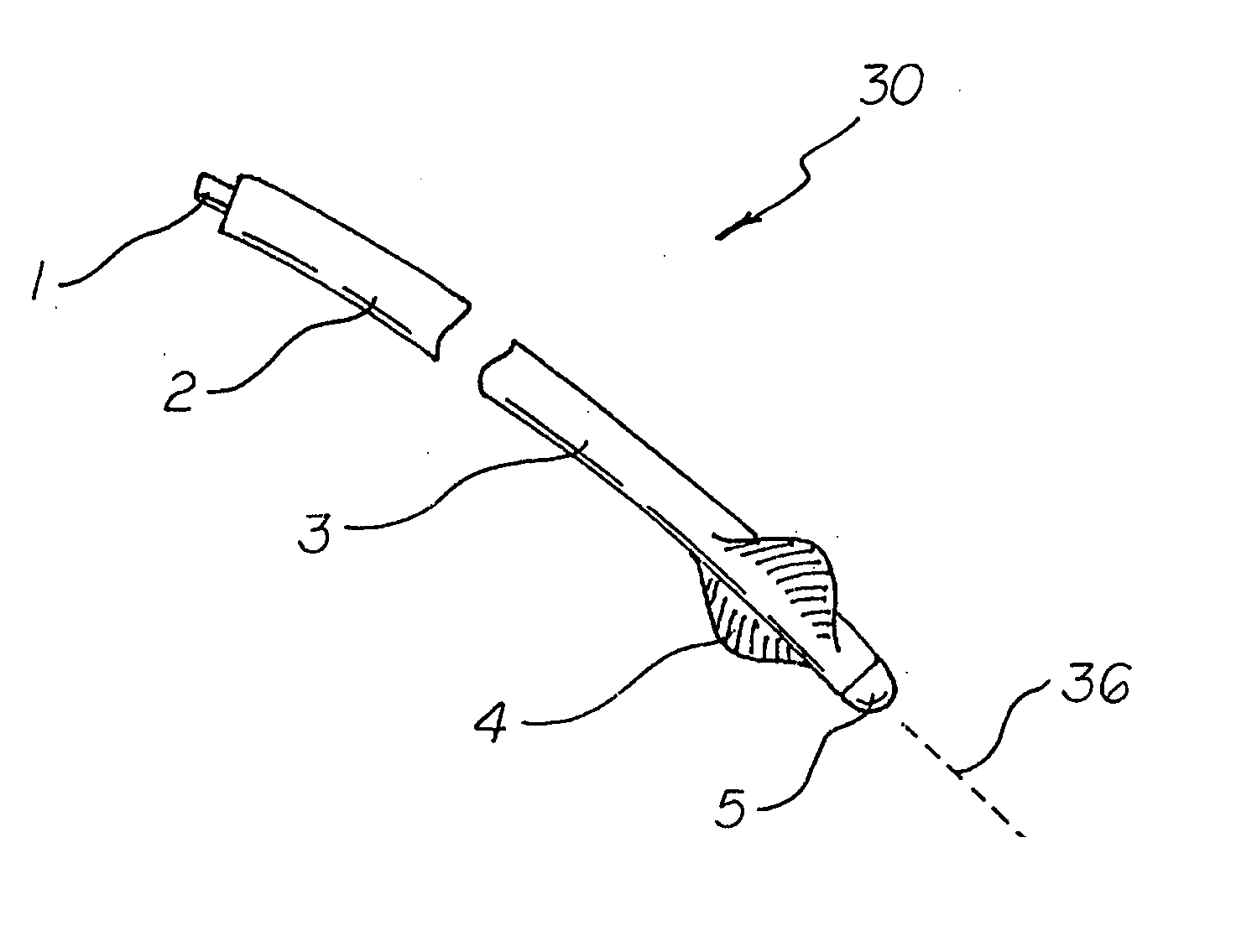
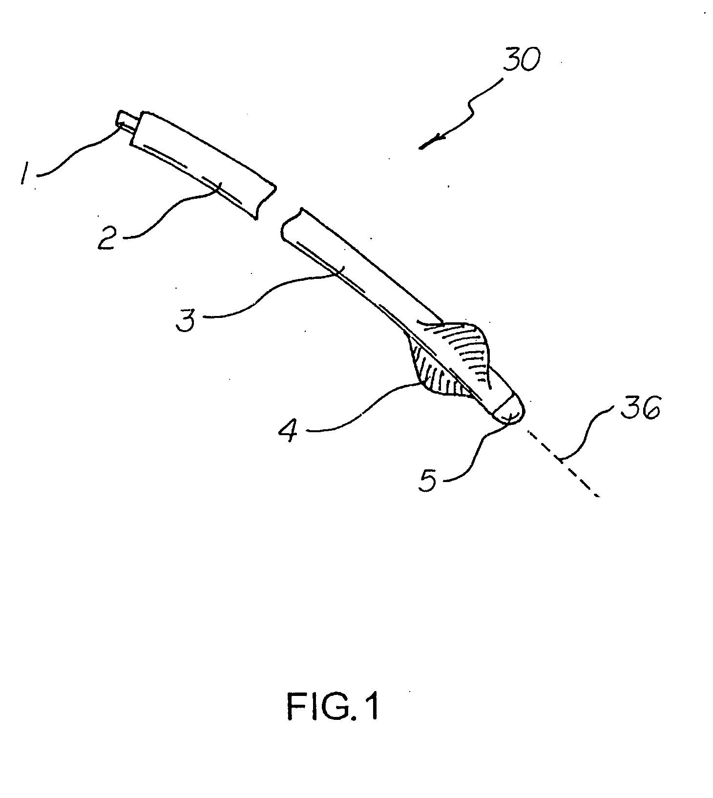
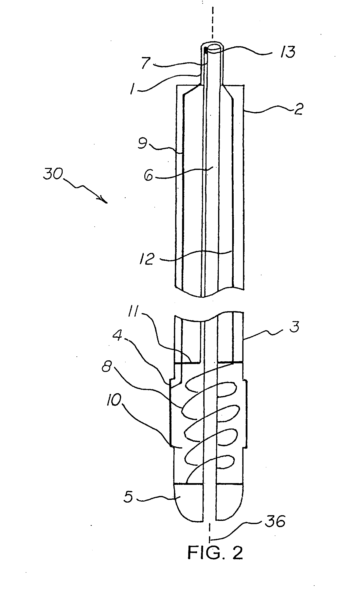
[0070] Turning to FIGS. 1-9, there is shown a first embodiment of the active fixation coronary sinus lead apparatus of the invention generally designated by reference numeral 30. In the first embodiment, active fixation coronary sinus lead apparatus 30 is shown with a pressure monitoring and helix torquing mechanism and selectively active electrode sectors for prevention of diaphragmatic stimulation.

[0071] Generally, an active fixation coronary sinus lead apparatus 30 includes electrode support means which include an electrode support longitudinal axis 36. A plurality of electrode segments 24 (also called active electrode segments 24) are supported by the electrode support means and are arrayed around the electrode support longitudinal axis 36. A plurality of insulation segments 26 (also called inac...


PUM


Abstract

An active fixation coronary sinus lead apparatus includes electrode support means which include an electrode support longitudinal axis. A plurality of electrode segments are supported by the electrode support means and are arrayed around the electrode support longitudinal axis. A plurality of insulation segments are supported by the electrode support means and are arrayed around the electrode support longitudinal axis at positions opposite to the electrode segments. In this respect, the insulation segments are interspersed between the electrode segments. Electrode segment orientation means are connected to the electrode support means for selectively orienting the electrode segments and the insulation segments around the electrode support longitudinal axis. Vessel anchoring means, which can include three flexible anchor wing portions, are connected to the electrode support means for anchoring the apparatus to an interior wall of a blood vessel. A pressure monitoring system can be connected to the vessel anchoring means for monitoring pressure inside the anchoring means.

Description

CROSS-REFERENCE TO RELATED APPLICATION [0001] This application claims priority based upon my copending Provisional Application Ser. No. 60 / 506,982; filed Sep. 29, 2003, which provisional application hereby is incorporated herein by this reference.BACKGROUND OF THE INVENTION [0002] 1. Field of the Invention [0003] The present invention relates generally to electrodes inserted in a patient, and, more particularly, to an active fixation coronary sinus lead apparatus especially adapted for insertion into a coronary blood vessel. [0004] 2. Description of the Prior Art [0005] Recently, it has been shown that patients with congestive heart failure and left bundle branch block benefit from resynchronization pacing therapy with simultaneous stimulation from the left and right ventricles. This has been shown to help patients feel significantly better and possibly live longer. Placement of the right ventricular lead is relatively easy and the lead technology available includes leads that have ...

Claims


Application Information

Patent Timeline
IPC IPC(8): A61N1/05
CPCA61N1/057A61N2001/0585A61N1/0573
Inventor VERMA, SUMIT
Owner VERMA SUMIT
Learn More