Method for establishing a foundation in particular for a tower of a wind energy plant

a technology for wind energy plants and foundations, which is applied in the field of method for establishing foundations in particular for wind energy plants, can solve problems such as overturning of foundation segments, delays but, and additional costs for remedying damage caused

Active Publication Date: 2005-04-07
WOBBEN ALOYS
View PDF39 Cites 47 Cited by
  • Summary
  • Abstract
  • Description
  • Claims
  • Application Information

AI Technical Summary

Benefits of technology

[0014] The invention is based on the realization that the problems occurring with methods to date can be avoided if the support poles are not screwed directly into the underside of the foundation segment, but instead are fixedly attached to distributed points on the foundation segment by means of supporting brackets, e.g., in the form of a support plate, before the foundation segment is set down on the subbase. The vertical adjustment means are still provided on the support poles, but elsewhere than hitherto, and the height of the segment is adjusted by screwing the support poles by different amounts into the underside of the foundation segment. The supporting brackets provide the foundation segment with a significantly larger supporting surface on the support poles, and hence a significantly improved distribution of load. This means that buckling of a threaded pole at the underside of the foundation segment will no longer occur.
[0017] In one preferred configuration, the support poles are each attached by means of support plates to a flange mounted on the underside of the foundation. The support plates are preferably bolted to the flange. This enables particularly good positioning and support of the foundation segment on the support poles to be achieved.

Problems solved by technology

This has resulted in the foundation segment overturning.
In addition to the dangers to which persons engaged in constructing the foundation were exposed, this has led not only to delays but also to additional costs for remedying the damage caused.

Method used


Image

  • Method for establishing a foundation in particular for a tower of a wind energy plant
  • Method for establishing a foundation in particular for a tower of a wind energy plant
  • Method for establishing a foundation in particular for a tower of a wind energy plant

Examples


Embodiment Construction

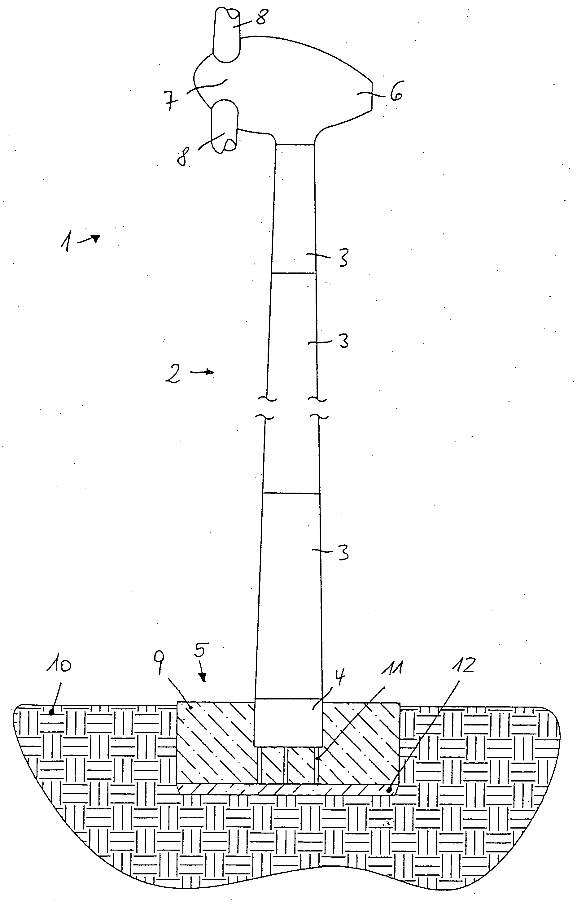
[0041] The wind turbine 1 shown schematically in FIG. 1 has a tower 2 comprising a plurality of segments 3, wherein the lowermost segment 4, the so-called foundation segment, is embedded in a foundation 5. A nacelle 6 is rotatably mounted at the top of the tower 2, and a rotor 7 with a plurality of blades 8 is attached to said nacelle. Disposed inside nacelle 6 is an electrical generator that is made to rotate by the wind forces acting on the rotor blades 8, thus generating electrical energy.

[0042] The segments 3, including foundation segment 4 of tower 2, are preferably steel elements, but generally can also be prestressed concrete elements into which prestressing steel elements or braces, for example, are cast. Foundation segment 4 is cast into a foundation block 9 that preferably consists of concrete. Said foundation block 9 may extend above the surrounding ground 10 or end level with the ground, but in any case covers the lower rim of the foundation segment 4 as well as the sup...


PUM


Abstract

The invention relates to a method for building a foundation for a structure comprising a plurality of segments, in particular for a wind turbine tower, a foundation segment for use in such method, and a wind turbine. In order to create a stable foundation, a method comprising the following steps is proposed on the basis of experience gained:_excavating a foundation bed,_building a stable, substantially level and horizontal subbase in a foundation bed, setting down a foundation segment of the structure on the subbase, wherein at least three vertically adjustable support poles are fixedly attached to said foundation segment by means of a supporting bracket mounted at the end of the support poles in such a way that only the support poles are placed onto predetermined points of support on the subbase,_producing a reinforcement on the subbase,_filling the remainder of the foundation bed with foundation mass, in particular concrete, to a level above the bottom rim of the foundation segment.

Description

BACKGROUND OF THE INVENTION [0001] 1. Field of the Invention [0002] The invention relates to a method for building a foundation for a structure comprising a plurality of segments, in particular for a wind turbine tower. The invention also relates to a support pole, a foundation segment for such a structure and a wind turbine. [0003] 2. Description of the Related Art [0004] Constructing a permanently stable and level foundation is of enormous importance for larger structures. Particularly in the case of a wind turbine tower, which can be more than 100 m in height and be exposed in operation to enormous forces, the foundation must conform to exacting specifications. [0005] Wind turbine foundations are currently constructed by firstly making a so-called subbase in a foundation bed, in other words a cement or concrete base layer that is as level and horizontal as possible. Support poles for setting down the foundation segment on the subbase are then mounted on the foundation segment, i....

Claims


Application Information

Patent Timeline
Patent Type & Authority Applications(United States)
IPC IPC(8): E02D27/32E02D27/01E02D27/42F03D1/00
CPCE02D27/42F03D11/045Y10S416/06Y02E10/728Y02B10/30F03D13/22Y02P70/50E02D27/32
Inventor WOBBEN, ALOYS
Owner WOBBEN ALOYS
Why Eureka
Try Eureka