Vehicle rear body structure

Inactive Publication Date: 2005-04-07
HONDA MOTOR CO LTD
View PDF10 Cites 37 Cited by
  • Summary
  • Abstract
  • Description
  • Claims
  • Application Information

AI Technical Summary

Benefits of technology

[0010] The rear body structure may further comprise a cross-member connected to and extending crosswise between the left and right floor frames. The cross-member also connects the left and right damper support members. By thus providing the cross member, the rigidity of the damper support members in a transversal direction of the vehicle is greatly improved. Preferably, the second portion of each of the gussets is also connected to the cross-member. This arrangement further increases the rigidity of a damper portion including the damper support members in the transversal direction of the vehicle. For the same purpose, the cross-member may be also connected to the body floor. Each of the wheel houses may include a reinforcing plate extending over and along an upper part of an inner member of the wheel house, and the first portion of each of the gusset is connected to the reinforcing pl

Problems solved by technology

To deal with this problem, an attempt may be made to increase the rigidity of the damper base 207 by increasing the thickness of the damper base 207, however, the thickened damper base

Method used


Image

  • Vehicle rear body structure
  • Vehicle rear body structure
  • Vehicle rear body structure

Examples


Embodiment Construction

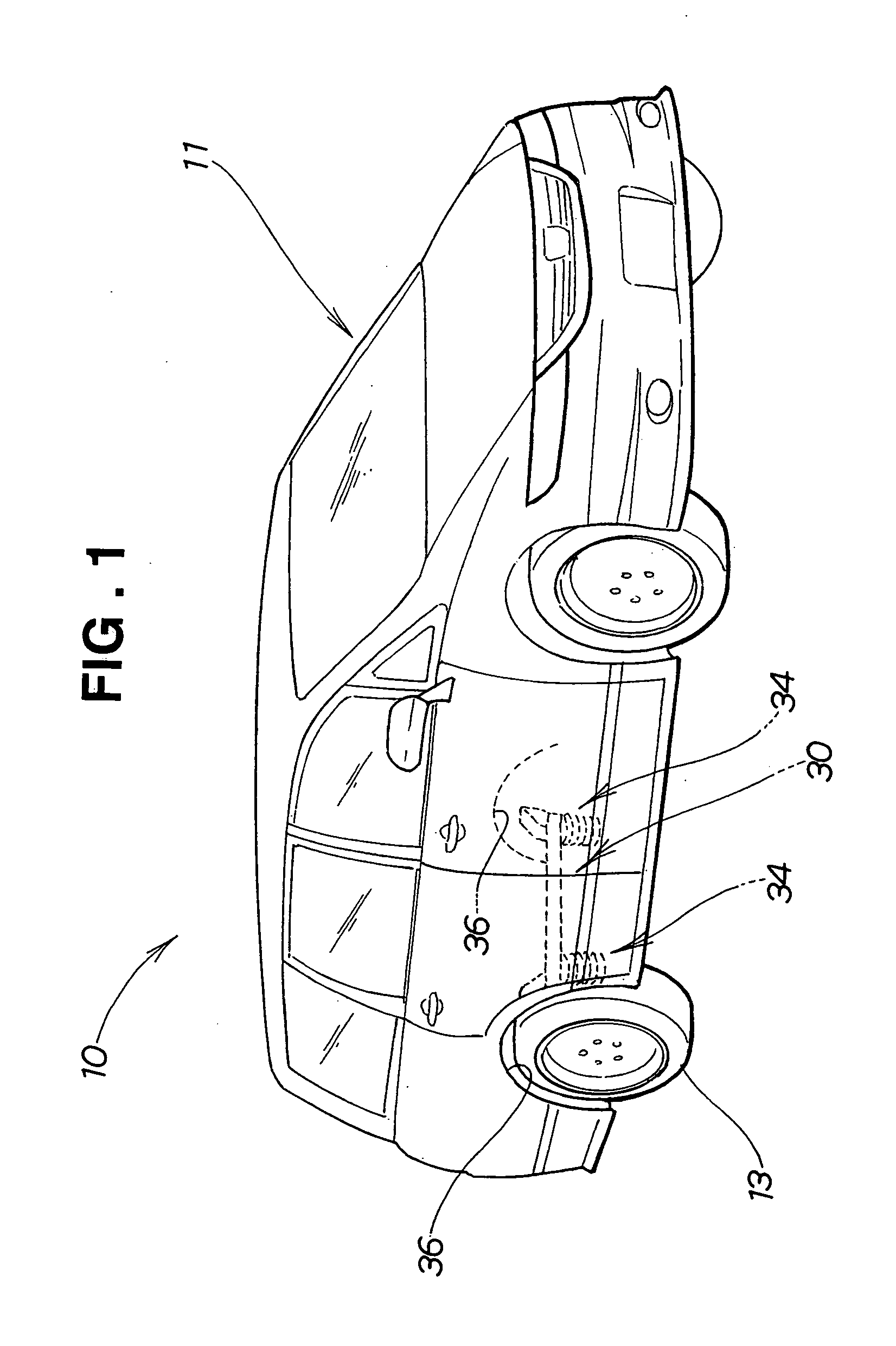
[0023] Referring now to the drawings and FIG. 1 in particular, there is shown in perspective a vehicle 10 having a body 11 including a rear body structure 30 according to an embodiment of the present invention.

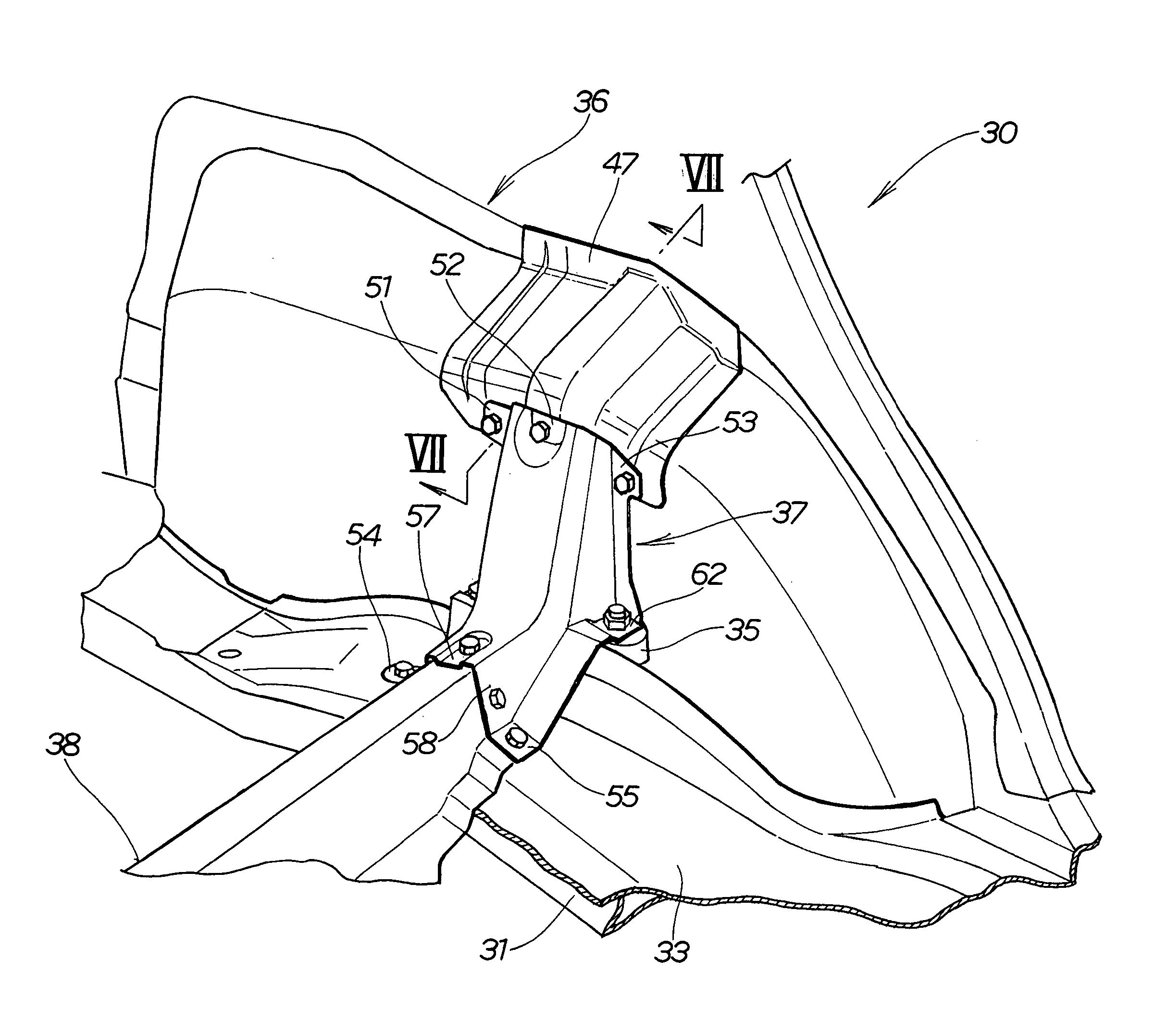
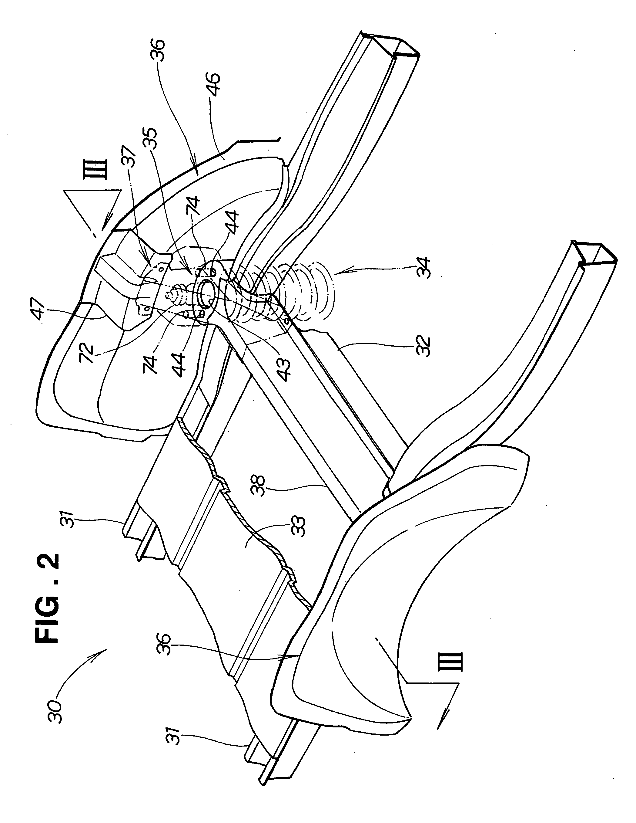
[0024] As shown in FIG. 2, the rear body structure 30 generally comprises left and right floor frames 31, 31 extending in a longitudinal (front-to-rear) direction of the vehicle 10 (FIG. 1), an under frame 32 connected to and extending crosswise between the left and right floor frames 31, 31, a body floor 33 mounted to the floor frames 31, 31 and the under frame 32, left and right damper support members 35, 35 (right one being shown in FIG. 3) mounted to the body floor 33 adjacent to the respective floor frames 31, 31 for supporting upper end portions of left and right dampers 34 (right one being shown in FIG. 3), respectively, left and right wheel houses 36, 36 disposed outwardly of the left and right damper support members 35, 35, respectively, in a transversal (widthwise) ...


PUM


Abstract

A rear body structure for a vehicle includes a gusset for reinforcing a body floor, each rear wheel house, and a damper support member disposed on the body floor adjacent to the wheel house. The gusset has a first portion connected to the wheel house, a second portion connected to the body floor, and a third portion connected to the damper support member and an upper end portion of a damper with the damper support member disposed between the third portion and the upper end portion of the damper. With this arrangement, a force applied from the damper to the damper support portion can be efficiently distributed through the gusset to the wheel house and the body floor.

Description

FIELD OF THE INVENTION [0001] The present invention relates to a vehicle rear body structure having a damper portion with improved rigidity and easiness of assembly. BACKGROUND OF THE INVENTION [0002] A typical example of conventional vehicle rear body structures is disclosed in Japanese Patent Laid-open Publication (JP-A) No. 2000-16338. The disclosed vehicle rear body structure, as shown in FIG. 10 hereof, includes a body floor 201, a wheel house 202 provided on the body floor 201 for covering an upper part of a rear wheel (not shown), a damper housing 204 disposed on the body floor 201 adjacent the wheel house 202 for supporting a damper 203, and a gusset 205 connecting a rear part of the wheel house to a side panel 216 and a rear panel 217 for reinforcing part of the rear body structure 200 in the vicinity of the wheel house 202 and the damper housing 204. [0003] The damper housing 204 has a vertical sidewall 206 connected to the wheel house 202 and a horizontal upper wall as a ...

Claims


Application Information

Patent Timeline
IPC IPC(8): B60G15/06B60J7/00B62D25/16
CPCB60G2204/1242B60G15/067
Inventor YAMAGUCHI, TOSHIYUKIOTSU, KAZUTAKA
Owner HONDA MOTOR CO LTD
Why Eureka
Try Eureka