
Light sources with nanometer-sized VUV radiation-absorbing phosphors

a radiation-absorbing phosphor, nanometer-sized technology, applied in the direction of discharge tube luminescnet screen, cellulosic plastic layered products, application of light-emitting coatings, etc., can solve the problem of reducing the electro-optical efficiency in the service life of the lamp, not helping to increase the efficiency of the lamp, and reducing the phosphor emissivity in the course of tim

Inactive Publication Date: 2005-04-07
GENERAL ELECTRIC CO
View PDF11 Cites 25 Cited by
  • Summary
  • Abstract
  • Description
  • Claims
  • Application Information

AI Technical Summary

Benefits of technology

"The present invention is related to a light source that emits electromagnetic radiation. The light source comprises a plasma discharge and a phosphor composition. The phosphor composition consists of particles that have at least two phosphors. The first phosphor absorbs the short-wavelength EM radiation and emits longer-wavelength EM radiation. The first phosphor can be nanometer-sized particles or transparent to the short-wavelength EM radiation. The second phosphor absorbs the long-wavelength EM radiation and emits visible light. The light source can be made by containing the plasma discharge in a sealed housing and disposing the phosphor composition inside. The source of plasma discharge can be mercury gas. The technical effects of this invention include improved lighting efficiency, reduced energy consumption, and improved color rendering."

Problems solved by technology

A drawback of known mercury low-pressure gas discharge lamps resides in that the action of UV radiation having very short wavelengths on the phosphor coating, the recombination of mercury ions and electrons on the phosphor surface, or the incidence of excited mercury atoms and electrons on the phosphor layer causes the emissivity of the phosphors to decrease in the course of time.
This emissivity loss results in a reduction of the electro-optical efficiency in the course of the service life of the lamp.
In addition, aluminum oxide does not emit any light, thus, does not help to increase the efficiency of the lamp.
This method would add some manufacturing cost because of the need to form an additional very dense top layer (the first layer) to protect the underlying phosphor layer.

Method used


Image

  • Light sources with nanometer-sized VUV radiation-absorbing phosphors

Examples


Embodiment Construction

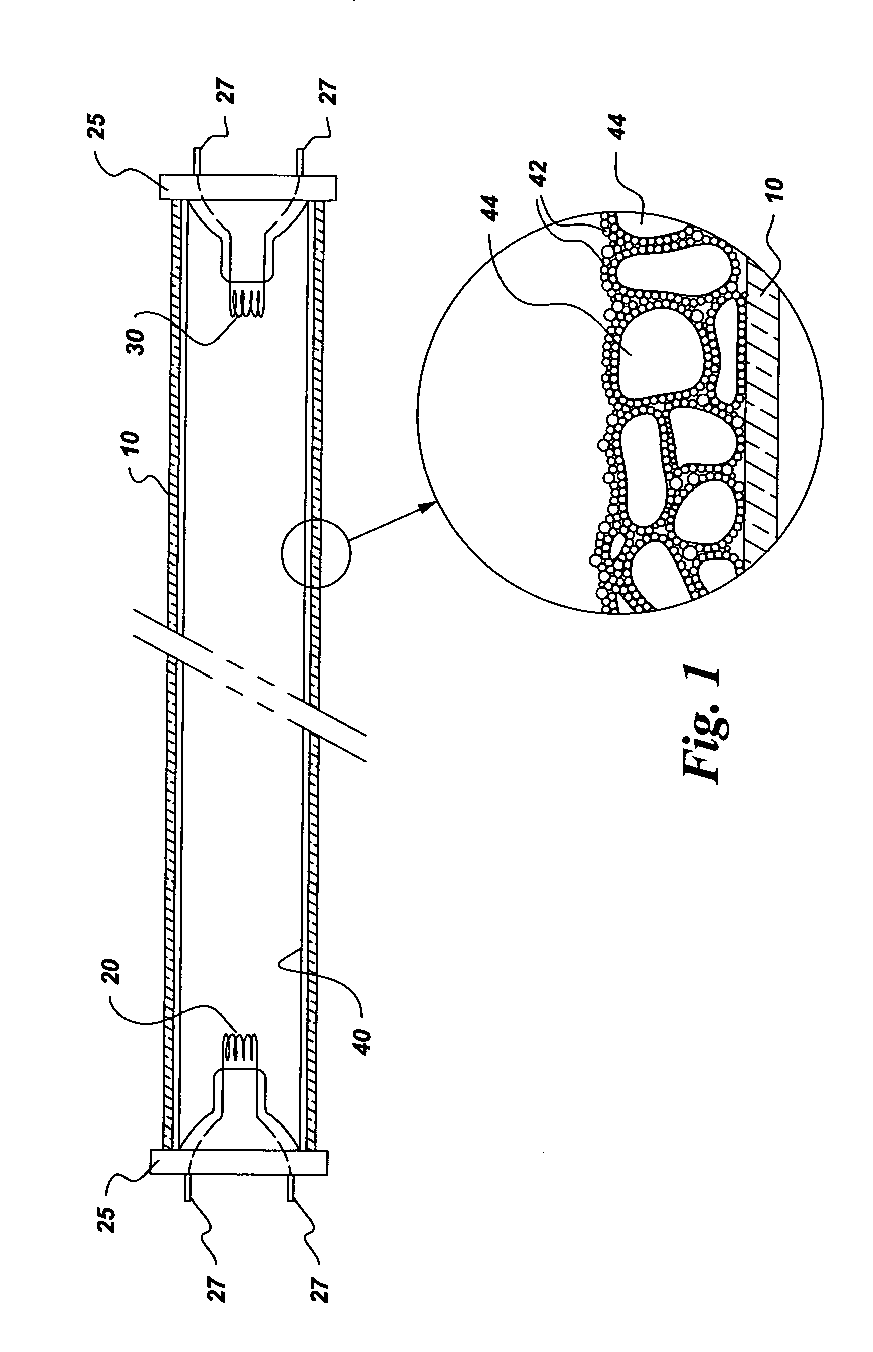
[0015] In the present disclosure, the terms “EM radiation” and “light” are used interchangeably. A light source, which is based on mercury gas discharge, comprises: (a) a source of plasma discharge that comprises mercury gas, which produces a plasma discharge that emits EM radiation, a portion of which has wavelengths shorter than about 200 nm; and (b) a phosphor composition that comprises a plurality of particles, each of said particle comprising at least a first phosphor and a second phosphor, said phosphor composition being disposed such that said first phosphor absorbs substantially said portion of EM radiation having wavelengths shorter than about 200 nm, and said first phosphor emitting EM radiation having wavelengths longer than about 200 nm.

[0016] According to one aspect of the present invention, the source of plasma discharge is contained in a sealed housing that is substantially transparent. The terms “substantially transparent” and “optically substantially transparent” m...


PUM

PropertyMeasurementUnit
wavelengthsaaaaaaaaaa
sizeaaaaaaaaaa
sizeaaaaaaaaaa

Abstract

A light source comprises: (a) a source of plasma discharge that emits electromagnetic radiation, a portion of which has wavelengths shorter than about 200 nm; and (b) a phosphor composition that comprises particles, each of the particles comprising at least a first phosphor and at least a second phosphor, the phosphor composition is disposed such that the first phosphor absorbs substantially the portion of EM radiation having wavelengths shorter than about 200 nm, and the first phosphor emits EM radiation having wavelengths longer than about 200 nm.

Description

BACKGROUND OF THE INVENTION [0001] The present invention relates to gas discharge devices. In particular, the present invention relates to gas discharge light sources having vacuum ultraviolet (“VUV”) radiation-absorbing phosphors. [0002] Light generation in mercury low-pressure gas discharge lamps is based on the principle that during the gas discharge, a plasma develops in the mercury-containing gas filling within a lamp and emits electromagnetic (“EM”) radiation predominantly in the ultraviolet (“UV”) wavelength range. The UV radiation emitted by a low-pressure mercury discharge concentrates at wavelengths of about 254 nm and about 185 nm. A phosphor, which is typically coated on the lamp housing, is employed to convert the UV radiation into visible light. [0003] A drawback of known mercury low-pressure gas discharge lamps resides in that the action of UV radiation having very short wavelengths on the phosphor coating, the recombination of mercury ions and electrons on the phosph...

Claims


Application Information

Patent Timeline
Patent Type & Authority Applications(United States)
IPC IPC(8): C09K11/08C09K11/02C09K11/66C09K11/67C09K11/70C09K11/74C09K11/77H01J1/62H01J9/22H01J61/44
CPCC09K11/02Y10T428/2993C09K11/666C09K11/668C09K11/673C09K11/701C09K11/7478C09K11/7704C09K11/7706C09K11/7709C09K11/7712C09K11/7734C09K11/7739C09K11/774C09K11/7769C09K11/777C09K11/7774C09K11/7777C09K11/778C09K11/7787C09K11/7792C09K11/7793C09K11/7797H01J61/44Y10S977/95Y10T428/2991C09K11/08
Inventor SRIVASTAVA, ALOK MANISETLUR, ANANT ACHYUTLOUREIRO, SERGIO MARTINSWILLIAMS, DARRYL STEPHENMANOHARAN, MOHAN
Owner GENERAL ELECTRIC CO
Learn More