Broad field motion detector

a motion detector and broad field technology, applied in the field of motion detectors, can solve the problems of ineffective monitoring of motion at or near walls, system or device protrusion and unattractiveness, and ineffective monitoring of motion through walls or entire rooms, so as to minimize potential adverse physiological effects, minimize interference with hearing aids, and efficiently utilize ultrasonic energy

Inactive Publication Date: 2005-04-07
THE WATT STOPPER
View PDF70 Cites 6 Cited by
  • Summary
  • Abstract
  • Description
  • Claims
  • Application Information

AI Technical Summary

Benefits of technology

[0007] The transmitter and receiver pair preferably transmit and receive ultrasound radiation at a frequencies above 20 KHz and more preferably at or near 40 KHz to minimize interference with hearing aides, and in order to minimize potentially adverse physiological effects. The preferred embodiments of the invention serve to disperse the transmitted waves and focus the received waves to efficiently utilize the ultrasonic energy that is returned at the sensor, such that the sensor's coverage area is optimized for given output energy and frequency.

Problems solved by technology

One of the shortcomings of current motion detector systems and devices is that they typically are only effective for detecting motion in a small area and are ineffective at monitoring motion at or near walls.
Despite the strategic positioning of the detector units, such devices and systems are ineffective at monitoring motion at or near walls or through an entire room.
Such systems or devices can be protrusive and unattractive.
Unfortunately, the energy of ultrasound waves at these higher frequencies are attenuated by air to a greater degree than lower frequencies.

Method used


Image

  • Broad field motion detector
  • Broad field motion detector
  • Broad field motion detector

Examples


Embodiment Construction

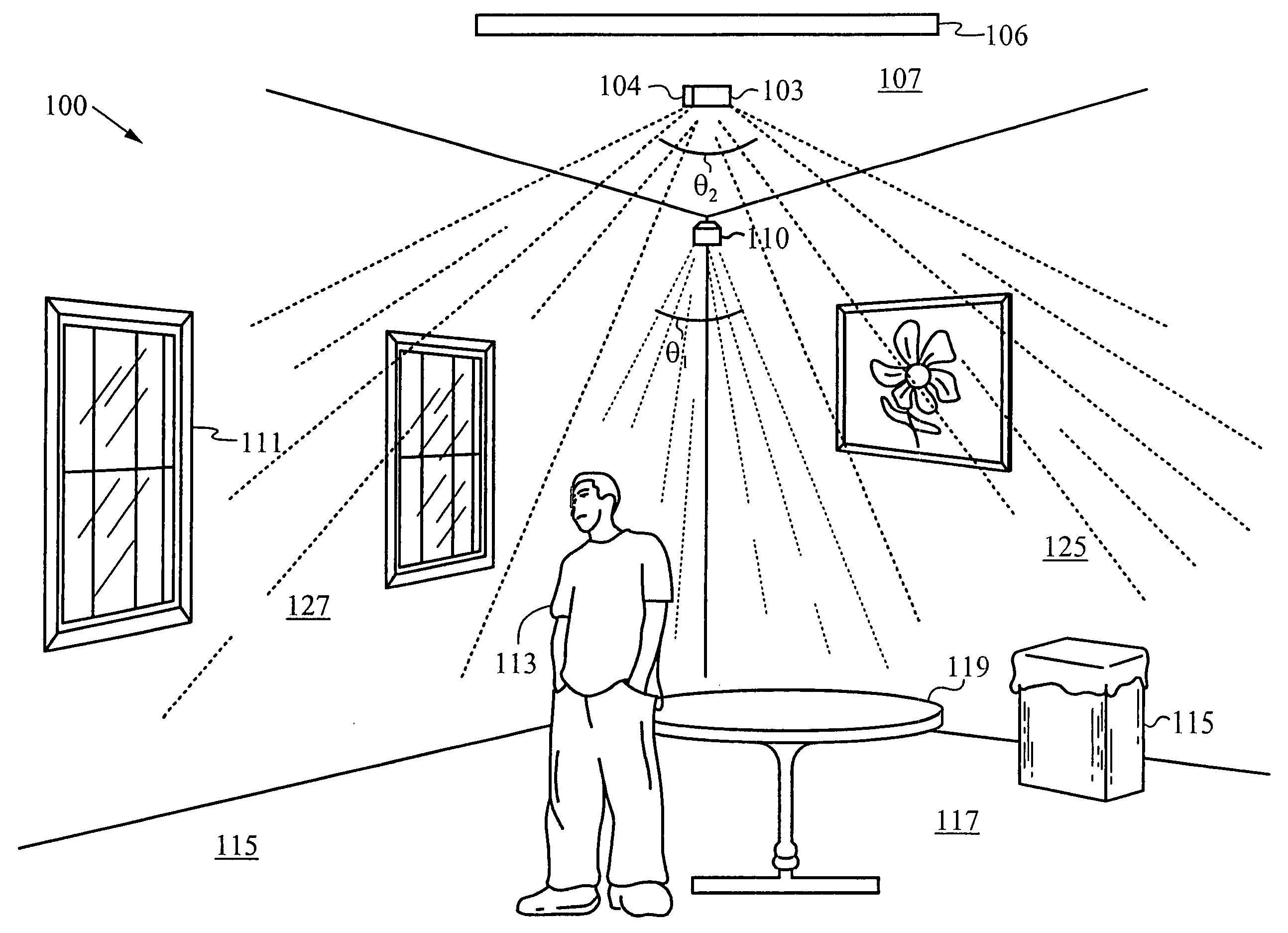
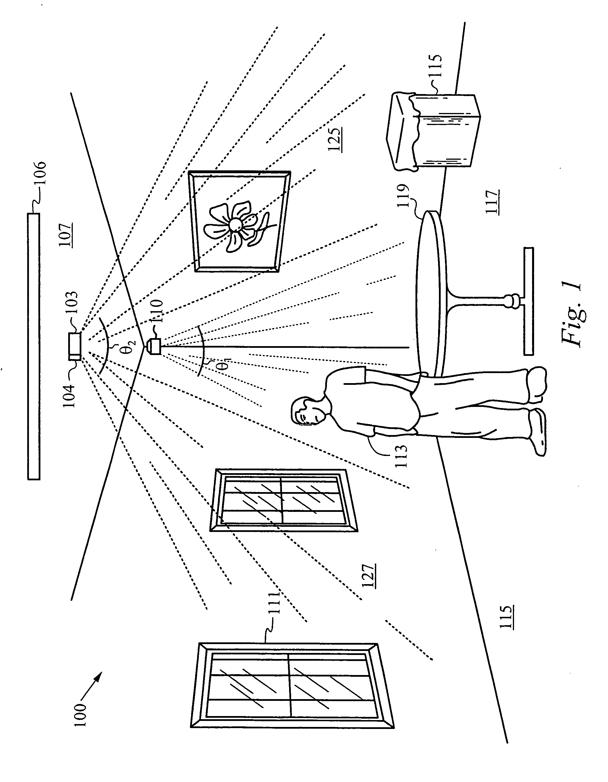
[0021]FIG. 1 shows a perspective view of a room 100 with a prior art ultrasonic motion detector 110 for broadcasting ultrasonic radiation in a first detection field. The first detection field generated by the prior art ultrasonic motion detector 110 typically has a small dispersion angel θ1, on the order of 30 degrees or less. Accordingly, to maximize the effectiveness of the motion detector 110, the detector 110 needs to be positioned in a corner and broadcast ultrasonic radiation out across the room to detect motion of objects, such as a table 119 or a person 113, in the center of the room. Regardless, of the strategic positioning of the prior art sensor 110, such prior art sensors are generally ineffective at detecting motion of objects in regions near the walls 125 and 127 or under the motion detection 110. For example, the detector 110, generally can not detect motion of the window 111 on the wall 127 or the garbage can 115 near the wall 125.

[0022] Still referring to FIG. 1, t...


PUM


Abstract

A motion sensing system device and method which utilize dispersed ultrasonic radiation is disclosed. The system preferably comprises a low profile sensor unit configured to couple to a ceiling position. The sensor unit comprises an ultrasonic transmitter and an ultrasonic receiver and a pair of acoustic reflectors positioned in a transmitting path of the ultrasonic transmitter and a receiving path of the ultrasonic receiver for generating and detecting the ultrasonic radiation in a broadcast field. The acoustic reflectors preferably comprise cones, conical cross-sections and/or combinations thereof which are integral with the ultrasonic transmitter and the ultrasonic receiver and/or are coupled to a housing structure for positioning the acoustic reflectors in the transmitting and/or receiving paths. The sensor unit also preferably comprises a circuit for driving the transmitter and for detecting motion by detecting changes in the receiver signal. In further embodiments, the system also includes an infrared sensor and is configured to generate a response based on the combination of changes in the receiver signal and a signal form the infrared sensor.

Description

FIELD OF THE INVENTION [0001] The invention relates to motion detectors. More particularly, the present invention relates to motion detectors which utilize ultrasonic radiation. BACKGROUND OF THE INVENTION [0002] A number of different motion detector systems are known. One type of motion detector utilizes ultrasonic radiation, such as described in U.S. Pat. No. 4,820,938 issued to Mix et al., the content of which is hereby incorporated by reference. In an ultrasonic motion detector, a detection field of ultrasonic radiation is generated and is monitored for Doppler shifts, which are indicative of motion. Such motion sensors are integrated with a light management system, wherein lights are turned off, turned on and / or are defined according to the detection of motion or a lack of detected motion. [0003] One of the shortcomings of current motion detector systems and devices is that they typically are only effective for detecting motion in a small area and are ineffective at monitoring ...

Claims


Application Information

Patent Timeline
Patent Type & Authority Applications(United States)
IPC IPC(8): G08B13/16
CPCG08B13/1618
Inventor JOHNSTON, KENDALL RYANVIALA, ROAR
Owner THE WATT STOPPER
Why Eureka
Try Eureka